

What Is a Biological Aerated Filter?
Biological aerated filter design sizes a submerged packed-bed reactor that oxidises BOD, nitrifies ammonia, and captures solids in one vessel. Industrial cells typically use 2–6 mm media at 2–4 m depth, hydraulic loading of 4–10 m/h, and EBCT of 20–60 minutes. Media grade and backwash rates decide if COD and ammonia targets are met without a secondary clarifier.
A BAF combines carbonaceous BOD oxidation, nitrification, and solids capture in a single packed bed. That definition comes from the 1999 Environmental Engineering Science review (Rogalla et al., 1999, doi:10.1089/ees.1999.16.201) and later work in Water Research and the Journal of Environmental Management. Modern cells use ceramic or granular polymer media 2–6 mm in size, upflow or downflow configuration, and co-current aeration, so COD, ammonia, and TSS leave one vessel without a secondary clarifier.
Recent hybrid studies keep the classical reactor and intensify it. Li et al. (2026, Water Research 303:126215, doi:10.1016/j.watres.2026.126215) showed that dosing nanoscale zero-valent iron (nZVI) into a granular-media BAF restored denitrification under chlorfenapyr stress by stabilising extracellular polymeric substances and accelerating electron transfer. Chen (2025, J Environ Manage 397:128226, doi:10.1016/j.jenvman.2025.128226) placed Fenton oxidation upstream of a BAF and removed 60–75% of refractory dissolved organic matter from landfill leachate that neither unit could treat alone. Both trains used submerged granular media.
For plant engineers, BAF sits between MBR and conventional activated sludge (CAS). Energy is typically 0.3–0.5 kWh/m³ versus 0.6–1.0 kWh/m³ for MBR because there is no membrane scouring air. Footprint is smaller than CAS because the media replaces a clarifier. That is why BAF still appears in specs for landfill leachate, food-processing reuse, textile dye wastewater, and small-to-medium municipal works at 10–2,000 m³/day when MBR OPEX is high or CAS plot area is missing.
Reactor Configuration: Upflow vs Downflow vs Floating Media
Upflow coarse-bubble aerated BAF — the Biofor and Biostyr-type geometry — is the most common industrial layout. Wastewater enters the bottom of the cell, air is injected through nozzles in the same upward direction, and treated effluent leaves over a launder at the top. Co-current upflow keeps the bed mobile, limits short-circuiting, and delivers dissolved oxygen across a 2–4 m media depth.
Downflow BAF sends water descending through the media while air rises from the bottom. Plug-flow behaviour can polish residual ammonia, but the descending water compacts the bed and raises head loss. Most plants we size for industrial FOG loads prefer upflow; downflow is more common in UK and US municipal plants treating settled sewage at TSS ≤ 60 mg/L.
Floating-media BAF uses expanded polystyrene or polyethylene beads at 0.3–0.6 g/cm³. The bed sits at the top of the cell, water flows upward through it, and a perforated plate retains the media. Full immersion helps nitrification in cold weather, yet low density caps organic loading and makes the geometry intolerant of high influent TSS. Cold-climate municipal packages and remote packaged plants still specify this form.
Upflow balances nitrification rate and solids handling but needs a stronger backwash system. Downflow polishes cleaner effluent but backwashes more often. Floating media is simple to operate but hits a loading ceiling sooner. The nZVI and Fenton+BAF studies both used submerged granular beds, which matches the dominance of upflow designs in current pilot and full-scale work.
Media Selection: Grade, Size, Density, and Surface Area
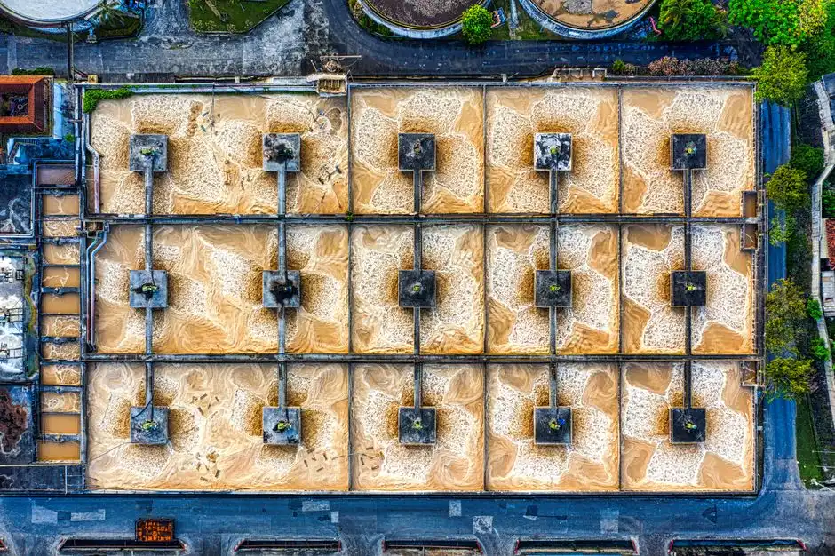
Filter media is the highest-impact decision in a BAF cell. It sets biofilm surface area, head loss growth, backwash frequency, and the split between carbonaceous BOD oxidation and nitrification. Thomas (2015, Virginia Tech) cites the BAF media testing method in Water Science and Technology 34:363-370, still the vendor qualification protocol referenced against the 1996 BAF media testing literature (doi:10.1016/0273-1223(96)00600-2).
Industrial BAFs use four main media classes. Expanded clay aggregates (1.4–1.8 g/cm³) suit most upflow submerged designs; sintered fly ash (1.6–2.0 g/cm³) fits sites with reliable local ash supply. Porous ceramics (2.0–2.4 g/cm³) win when specific surface area matters more than cost; granular sunken polymer (1.05–1.2 g/cm³) serves low-density upflow cells. Effective size sits in a 2–6 mm envelope, with uniformity coefficient typically below 1.6 to limit stratification.
| Media class | Effective size (mm) | Bulk density (g/cm³) | Specific surface area (m²/m³) | Porosity (%) | Typical 2026 application |
|---|---|---|---|---|---|
| Expanded clay | 2.5–5.0 | 1.4–1.8 | 1,200–1,800 | 45–55 | Upflow industrial BAF, food and textile |
| Sintered fly ash | 3.0–6.0 | 1.6–2.0 | 1,000–1,500 | 40–50 | Upflow municipal BAF, landfill leachate |
| Porous ceramic | 2.0–4.0 | 2.0–2.4 | 1,800–2,400 | 40–50 | High-rate polishing, refractory DOM |
| Granular polymer (sunken) | 3.0–5.0 | 1.05–1.2 | 1,000–1,400 | 45–60 | Low-density upflow, low-strength municipal |
Three media parameters drive sizing. Specific surface area controls biofilm carrying capacity — at 1,500 m²/m³, a 200 m³ media bed hosts about 3,000 m² of active biofilm per cell. Porosity in the 40–60% range sets interstitial volume, effective hydraulic retention, and head loss rise. Density decides whether a retention grid is needed and how hard the backwash system must fluidise the bed. Hybrid nZVI-BAF and Fenton-BAF trains rely on stable expanded clay or porous ceramic so the grains host biofilm and surface iron chemistry at once.
Which porous filter media suit consumer water?
Porous ceramic and expanded clay are the packed-bed grades used for industrial and municipal BAF water, not consumer cartridge inserts. Ceramic at 2.0–4.0 mm and 1,800–2,400 m²/m³ suits high-rate polishing; expanded clay at 2.5–5.0 mm and 1,200–1,800 m²/m³ is the default upflow choice for food and textile loads. Consumer water porous filter media in point-of-use cartridges lack the density and backwash tolerance required for a BAF cell hydraulic envelope.
Hydraulic and Organic Loading Envelopes
Three numbers set BAF cell size: hydraulic loading rate (HLR), organic loading rate (OLR), and empty bed contact time (EBCT). They move together, yet each answers a different question. HLR drives footprint, OLR drives media volume, and EBCT drives effluent ammonia at a stated wastewater temperature.
For submerged-media industrial BAF, HLR typically sits in the 4–10 m/h range based on Thomas (2015) low-loading submerged-media data and vendor envelopes. The lower end applies to high-strength industrial influents (COD > 1,000 mg/L) and to Fenton+BAF trains where upstream oxidation already cut part of the load. The upper end applies to low-strength polishing. OLR for carbon-oxidation BAF runs 0.5–4 kg BOD/m³·day; dedicated nitrification BAF ammonia loading runs 0.1–0.5 kg NH₃-N/m³·day. EBCT usually falls between 20 and 60 minutes, with longer values for nitrification duty or cold influent (< 12 °C), where nitrifier growth rate halves for every 7 °C drop.
| Design parameter | Carbon-oxidation BAF | Nitrification BAF | Fenton+BAF (refractory) |
|---|---|---|---|
| Hydraulic loading rate (m/h) | 4–10 | 2–6 | 3–6 |
| Organic loading rate (kg BOD/m³·day) | 0.5–4.0 | 0.2–1.0 | 0.3–1.5 |
| Ammonia loading (kg NH₃-N/m³·day) | 0.1–0.3 | 0.1–0.5 | 0.1–0.3 |
| EBCT (minutes) | 20–45 | 30–60 | 30–60 |
| Target effluent COD (mg/L) | ≤ 60 | ≤ 80 | ≤ 100 |
| Target effluent NH₃-N (mg/L) | ≤ 5 | ≤ 1 | ≤ 5 |
The 1999 Rogalla review documented combined ammonia, carbonaceous, and solids removal in one BAF — the same envelope still quoted on vendor datasheets. At fixed design flow, OLR sets media volume, media depth sets bed area, and bed area at a chosen HLR gives footprint. EBCT is then checked against the nitrification rate constant at design temperature to confirm ammonia compliance.
How are multi-media filter design calculations set?
Multi-media filter design calculations size layered sand, anthracite, and garnet beds for physical solids capture, not for attached-growth BOD or ammonia removal. Filtration rate, media depth, and backwash expansion set the vessel; they do not replace BAF HLR, OLR, or EBCT checks. When a reuse train needs both polishing filtration and biological treatment, pair the BAF cell with a separate Multi-Media Filter for Water Treatment downstream rather than merging the two calculation methods into one bed.
Backwash Sequencing and Air/Water Sizing
Backwash is the operating detail that makes or breaks a BAF. Head loss across the media bed rises as biofilm thickens and solids are captured; once it reaches 0.8–1.2 m water column, the cell must come off-line. A typical sequence runs drain-to-bed → air scour alone → combined air + water → water-only rinse → return to service, and the full cycle takes 20–40 minutes.
Backwash interval for submerged-media industrial BAF is 24–72 hours, driven by influent TSS, biofilm growth, and terminal head loss. Backwash air flux sits at 40–60 m/h and water flux at 15–30 m/h — the values used to size the scour blower and backwash pump. The combined air + water phase fluidises the bed, strips excess biofilm, and releases captured solids. Air alone comes first so the sludge blanket is not driven deep into the bed when water starts.
Backwash wastewater is typically 3–8% of treated flow. It carries TSS of 1,000–3,000 mg/L and partially degraded BOD, and must return to the head of the plant or thicken in a DAF system for high-FOG or high-TSS industrial streams before sludge handling. Under-sized backwash pumps cause media carryover and visible effluent solids; over-sized pumps fracture grains and shorten bed life from 12–15 years to 6–8 years. Size for peak solids days, not averages — a 24–72 hour interval can collapse to 8–12 hours, and the backwash system must keep up.
Integration With Pretreatment and Post-Treatment Units
BAF is intolerant of high TSS, oil, and hydraulic shock. A complete process train puts fine screening, grit removal, and flow equalisation ahead of the cells, then polishing or disinfection after them. Rags blind the underdrain, oil coats the media and kills biofilm, and a 2× hydraulic surge scours the bed and washes out biomass.
Upstream, install a rotary fine bar screen at 3–5 mm aperture ahead of the BAF feed well — coarser screens let fibres through and they accumulate at the underdrain. Add a flow equalisation basin sized for at least 6 hours of average flow to dampen batch discharges from chemical or food plants. For high-FOG dairy, meat, or edible-oil streams, a DAF system for high-FOG or high-TSS industrial streams ahead of the BAF is not optional. That DAF protects the bed and can cut backwash frequency by 30–50%.
Downstream, BAF effluent is typically <10 mg/L TSS, <60 mg/L COD, and <5 mg/L NH₃-N. For water-reuse duty, an MBR polish, RO, or both follow. The 2025 Fenton+BAF leachate study positions BAF between Fenton oxidation and downstream RO, with the BAF removing 40–60% of remaining COD and 70–85% of ammonia after Fenton has cut refractory DOM. For final disinfection before reuse or discharge, chlorine dioxide disinfection at 1–2 mg/L residual gives 3-log bacterial inactivation without forming the trihalomethanes associated with chlorine at high organics.
Biological Aerated Filter Design Versus MBR and CAS
Procurement defence needs a head-to-head comparison of BAF, MBR, and CAS envelopes, not a single datasheet. The table below uses municipal or light-industrial influent (COD 250–600 mg/L, NH₃-N 20–50 mg/L, TSS 150–300 mg/L) and a reuse-quality effluent target (COD ≤ 50 mg/L, NH₃-N ≤ 5 mg/L, TSS ≤ 10 mg/L).
| Parameter | BAF | MBR | Conventional activated sludge |
|---|---|---|---|
| Effluent COD (mg/L) | 40–80 | 20–40 | 30–60 |
| Effluent NH₃-N (mg/L) | 0.5–5 | 0.2–2 | 1–5 |
| Effluent TSS (mg/L) | 10–30 | ≤ 2 | 10–20 |
| Footprint (relative) | 0.4–0.6× | 0.6–0.8× | 1.0× (baseline) |
| Energy (kWh/m³) | 0.3–0.5 | 0.6–1.0 | 0.25–0.45 |
| CAPEX (relative, 500 m³/d) | 1.0× (baseline) | 1.6–2.0× | 0.9–1.1× |
| OPEX driver | Backwash water + air | Membrane replacement + scour air | Sludge handling + clarifier maintenance |
| Reuse suitability | Good with RO polish | Excellent direct | Needs tertiary filter |
| Media/membrane life | 8–15 years (media) | 5–10 years (membranes) | N/A |
BAF wins on energy and footprint: no membrane scouring aeration, no secondary clarifier, and the media bed replaces both. Weaknesses are intolerance to high TSS or oil — which forces the pretreatment train above — and media replacement every 8–15 years. Hybrid trains are now common: Fenton+BAF for landfill leachate, nZVI-BAF for pesticide wastewater, and BAF followed by an MBR polishing step for industrial reuse. CAS remains the lowest CAPEX option above about 5,000 m³/day, but loses on footprint and tertiary polish cost.
Specify BAF for 10–2,000 m³/day with moderate influent variability and a reuse target that allows RO downstream. Specify MBR when direct reuse without RO is required and CAPEX is available. Specify CAS for very large flows where footprint is open and skilled operators are present. A WSZ underground integrated treatment skid typically embeds a small BAF cell for BOD and ammonia removal in residential applications.
Worked Sizing Example: Industrial BAF for 500 m³/d
A 500 m³/d chemical or food-processing BAF resolves as follows at 21 m³/h design flow, influent COD 500 mg/L, NH₃-N 40 mg/L, and TSS 150 mg/L.
| Parameter | Value | Source / basis |
|---|---|---|
| Design flow | 21 m³/h (500 m³/d) | Plant influent |
| Influent BOD (assumed) | 280 mg/L | COD/BOD ratio ≈ 1.8 |
| BOD load | 5.9 kg BOD/h | 280 mg/L × 21 m³/h |
| Organic loading rate target | 1.5 kg BOD/m³·day × 24 = 36 kg/d | Mid-range for industrial BAF |
| Required media volume | 5.9 / 1.5 = 3.9 m³/h × 24 = ~94 m³ (per day basis 200 m³ total at 1.5 kg/m³·day) | Design rule |
| Media depth | 3.0 m | Standard for upflow submerged BAF |
| Bed area | 200 / 3 = ~67 m² (rounded to 2 cells × 33 m²) | Area = volume / depth |
| Hydraulic loading rate | 21 / 67 = 0.31 m/h | Low-rate industrial; well below 4 m/h envelope |
| EBCT | 3.0 / 0.31 × 60 = ~580 min (conservative; at 4 m/h would be 45 min) | EBCT = depth / HLR |
| Backwash water | ~5% of treated flow = 25 m³/d | Returned to headworks |
| Backwash interval | 48 h (estimated; verify with pilot) | Head loss trigger |
| Target effluent | COD ≤ 60 mg/L, NH₃-N ≤ 5 mg/L, TSS ≤ 20 mg/L | Design basis |
The 1.5 kg BOD/m³·day OLR and 3 m media depth give about 200 m³ of media in two cells — one cell can stay online while the other backwashes. The chosen HLR of 0.3 m/h is conservative; pushing to 2–4 m/h would shrink bed area to 5–10 m² and need a taller cell, a plot-plan choice rather than a process limit. Most plants we size for food or chemical duty run at the lower end of HLR until a pilot confirms ammonia at design temperature.
Who This Is For and Next Step
Plant engineers, EPC contractors, and procurement managers sizing a BAF train at roughly 10–2,000 m³/day with moderate FOG and TSS after pretreatment are the primary readers for this guide. Teams that need membrane-quality TSS without RO, or that lack grit and oil removal upstream, should look at MBR-first layouts instead. To translate media volume, backwash air/water rates, and pretreatment into a vendor package, send your influent COD, NH₃-N, TSS, and flow profile through a BAF design inquiry.
Frequently Asked Questions
What is the typical hydraulic loading rate for an industrial BAF?
For submerged-media industrial BAF the hydraulic loading rate runs 4–10 m/h in standard duty, with 2–6 m/h typical for nitrification-only cells and 3–6 m/h for Fenton+BAF trains handling refractory influent. Designs above 10 m/h are possible but need pilot confirmation to keep ammonia within target at the design wastewater temperature. Always pair the chosen HLR with an EBCT check at the coldest expected month.
How often does a BAF need backwashing, and what air and water rates are required?
Backwash interval is 24–72 hours, triggered when head loss across the media bed reaches 0.8–1.2 m water column. Backwash air flux of 40–60 m/h and water flux of 15–30 m/h are the standard design values for granular-media BAF. The full sequence — drain, air scour, combined air + water, water rinse — takes 20–40 minutes per cell and should be sized for peak solids days.
What is the typical media life, and how does BAF compare to MBR for industrial reuse?
Granular BAF media lasts 8–15 years if backwash rates are correctly sized; over-pumping fractures grains and shortens life to 6–8 years. Against an MBR polishing step, BAF uses less energy (0.3–0.5 versus 0.6–1.0 kWh/m³) at small-to-medium flows. MBR delivers lower TSS (≤ 2 versus 10–30 mg/L) and can feed RO directly without an extra polish.
Can BAF handle landfill leachate or other refractory industrial wastewater?
Yes, but only as a polishing stage after an advanced oxidation step. Chen (2025, J Environ Manage, doi:10.1016/j.jenvman.2025.128226) showed Fenton upstream of a BAF removed 60–75% of refractory dissolved organic matter that neither unit could treat alone. The BAF then delivered 40–60% COD removal and 70–85% ammonia removal on the Fenton effluent.