Why Grand Rapids Transportation Plants Are Under Heightened Pretreatment Scrutiny
A Tier-1 automotive parts or heavy-truck body supplier discharging to the Grand Rapids Water Resource Recovery Facility (WRRF) sits on top of two stacked regulatory floors. The federal floor is EPA 40 CFR 403, the General Pretreatment Regulations, which define categorical pretreatment standards and require industrial users to remove or neutralize pollutants before discharge to a publicly owned treatment works (POTW). The operative local floor is the Grand Rapids WRRF industrial-user discharge ordinance, administered under the City of Grand Rapids and applied to users in Kent County and adjacent service areas; it caps FOG, TSS, COD, and metals (Zn, Ni, Pb, Hg) at values frequently tighter than the federal categorical pretreatment maxima. The WRRF acts as the Control Authority and has authority to issue industrial discharge permits, conduct sampling, and impose surcharges or consent orders.
Transportation equipment plants are a targeted sector because their wastewater chemistry lines up exactly with the parameters the WRRF and EPA watch hardest. FOG loads from stamping lubricants, machining coolants, and parts-washer effluent routinely push oil and grease above 500 mg/L on the raw side. E-coat and phosphating rinse water carry dissolved zinc and nickel plus high phosphate, and alkaline cleaners drive pH excursions into the 10-12 range during batch dumps. The cost of skipping engineered pretreatment is concrete: a single zinc exceedance in a 24-hour composite sample is enough to trigger a POTW surcharge, a Notice of Violation, and, on repeat, a consent order that can force a six-figure CAPEX retrofit on the plant's own dime (per EPA 40 CFR 403 enforcement framework). Specifying the right unit-operation train is materially cheaper than absorbing either the surcharges or the emergency retrofit.
The Wastewater Fingerprint of a Transportation Equipment Plant
A Tier-1 supplier in western Michigan typically generates seven distinct process streams, each with its own pollutant signature. The treatment train has to be designed against this fingerprint, not against a generic "industrial wastewater" profile. The seven streams are:
- E-coat / electrodeposition rinse — continuous flow, 50-200 mg/L TSS, trace Zn/Ni from the coating bath, COD 200-600 mg/L.
- Phosphating rinse — continuous or semi-batch, COD 500-2,000 mg/L, high phosphate (often 50-200 mg/L PO₄), low TSS.
- Machining coolant overflow — batch, oil and grease 500-5,000 mg/L, suspended solids 200-1,000 mg/L, often with tramp fluid hydraulics.
- Aqueous parts-washer effluent — batch, FOG 200-2,000 mg/L, pH 9-11, surfactant load that foams in DAF cells if not antifoam-dosed.
- Hydraulic test water — batch, low COD but episodic flow spikes, trace mineral oil from test rigs.
- Assembly lubricant condensate — low volume, but FOG 1,000-10,000 mg/L when it does arrive.
- General shop-floor wash water — continuous, low-to-moderate TSS (100-400 mg/L), low metals, but high in FOG from floor cleaning.
The batch streams — parts-washer dumps and hydraulic test water — are the reason equalization is non-negotiable. A 500-gallon parts-washer dump over 30 minutes can swing zinc, FOG, and pH in the combined sewer by an order of magnitude. Without 8-24 hours of equalization volume, the downstream DAF and precipitation stages see those swings as a moving target, and removal efficiency collapses. Dissolved metals and high COD are also the reason DAF alone is insufficient: flotation removes emulsified oils and suspended solids but does not precipitate dissolved zinc or nitrate-soluble nickel, and does not break down soluble COD. The unit-operation train has to continue past DAF into chemical precipitation and biological polishing.
The 2026 Unit-Operation Train: From Headworks to Discharge
The process train a 2026-spec western Michigan plant should deploy runs in seven blocks, in this order. Skipping or reordering blocks is the most common root cause of permit excursions documented in the field (HydropureWater field data, 2026).
Block 1 — Headworks. A GX rotary mechanical bar screen with 3-6 mm openings removes rags, plastic strapping, and stringy machining debris before they foul downstream transfer pumps and the DAF nozzle ring. Without it, rag accumulation is the #1 cause of DAF cell pump cavitation events.
Block 2 — Equalization. An above-grade surge tank sized to 8-24 hours of average daily flow, with mechanical mixing and pH/temperature probes. Plants with intermittent parts-washer or hydraulic-test discharges need the upper end of that range.
Block 3 — Dissolved air flotation. The dissolved air flotation system (4-300 m³/h, micro-bubble 10-50 μm) targets 90-95% FOG removal and 85-95% TSS removal when paired with a PLC-controlled coagulant and flocculant dosing system (typical: 50-150 mg/L polyaluminum chloride + 1-3 mg/L anionic flocculant). Automatic skimming pulls the float layer; underflow discharges to sludge handling. The DAF is the highest-impact single block in the train and is the first piece of equipment a plant under a consent order should install — see the emergency DAF deployment for a high-FOG truck-stop lagoon for a worked example.
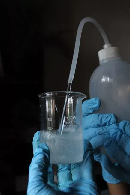
Block 4 — Chemical precipitation for metals. Raise pH to 9.0-9.5 with NaOH to precipitate dissolved zinc and nickel as hydroxides (zinc precipitation pH 9 is the textbook minimum solubility point; nickel requires 9.5-10 for full removal). Clarify in a lamella settler or recycle the precipitated stream back through the DAF for combined sludge handling. Jar testing is mandatory at this stage — actual metal speciation in e-coat effluent rarely matches textbook curves because of chelating agents in the bath.
Block 5 — Biological or MBR polishing. A conventional activated sludge stage works, but an MBR membrane bioreactor polishing system (DF series flat-sheet PVDF, 0.1 μm nominal pore) drops BOD from 200-500 mg/L to <5 mg/L and TSS to <5 mg/L in a single tank, occupying roughly 60% less footprint than conventional activated sludge with a separate clarifier. This is the block that turns a "meets the limit" plant into a "passes any future lower limit" plant. For a benchmark, see the BMW automotive plant wastewater treatment engineering breakdown.
Block 6 — Disinfection. A chlorine dioxide generator provides reliable microbial control before sewer discharge; the system is rated for both EPA and WHO potable-water reuse compliance, which gives a margin of safety for industrial discharge.
Block 7 — Sludge handling. A plate-and-frame sludge dewatering filter press dewaters both the DAF skimmings and the waste activated sludge from the MBR to 30-40% dry solids for off-site disposal, cutting hauling volume by 80-90% versus liquid sludge. For sizing on the oily condensate stream specifically, the DAF sizing guide for compressor oily condensate walks through the hydraulic calculation.
Design Parameters and 2026 Effluent Targets for Western Michigan
The table below consolidates raw influent, the Grand Rapids WRRF's typical local discharge limits (per the WRRF industrial user discharge ordinance, 2025-08 revision), and the effluent quality a properly sequenced DAF + precipitation + MBR train actually achieves in service (HydropureWater field data, 2026).
| Parameter | Typical Raw Wastewater | WRRF Local Limit (typical) | DAF-only Effluent | DAF + Precipitation + MBR Effluent |
|---|---|---|---|---|
| BOD₅ | 200-500 mg/L | ≤ 250 mg/L (local cap; EPA categorical often 300) | 150-300 mg/L | < 5 mg/L |
| TSS | 200-1,000 mg/L | ≤ 200 mg/L | 20-50 mg/L | < 5 mg/L |
| FOG (O&G) | 500-5,000 mg/L | ≤ 100 mg/L (WRRF cap) | 10-50 mg/L | < 5 mg/L |
| COD | 500-2,000 mg/L | ≤ 600 mg/L | 300-800 mg/L | < 50 mg/L |
| Zinc (Zn) | 2-20 mg/L | ≤ 1.0 mg/L (typical local cap; tightening in 2026) | 1-5 mg/L (insufficient) | < 0.5 mg/L after pH 9.0-9.5 precipitation |
| Nickel (Ni) | 1-10 mg/L | ≤ 0.5 mg/L (typical local cap) | 0.5-3 mg/L (insufficient) | < 0.2 mg/L after pH 9.5-10 precipitation |
| pH | 6-11 (batch swings) | 6.0-10.0 (continuous; 5.0-11.0 instantaneous per 40 CFR 403) | 6.5-9.5 | 7.0-8.5 |
The WRRF's local limits are often stricter than EPA categorical pretreatment maxima — the FOG cap of 100 mg/L is a frequent flashpoint, as is the zinc cap, which automotive OEM water-stewardship commitments are pushing downward in 2026 toward sub-1.0 mg/L territory. Meeting the limit on a 24-hour composite is not the same as passing the audit: the WRRF may also take grab samples, and equalization is what flattens the peak excursions that grab sampling catches. A DAF-only train is not enough when the local cap on FOG is 100 mg/L and the raw stream is 3,000 mg/L; the math only closes with a precipitation and MBR polish downstream.
How a Real Plant Sequences Installation: A 2026 Implementation Pattern
The plants that get out of consent orders fastest follow a four-phase pattern rather than a single mega-CAPEX. Phase 1 — Audit and jar testing (4-8 weeks). Pull 24-hour composites from each of the seven process streams; run coagulant and flocculant jar tests; confirm DAF chemistry and the actual zinc/nickel precipitation pH curve for the specific bath chemistry. This is the step most plants skip, and it is the step that prevents the most expensive downstream mistakes. Phase 2 — Headworks and DAF (8-16 weeks). Install the rotary bar screen and the DAF as the first permanent equipment. This single block removes 85-95% of the FOG and TSS load and typically halts permit excursions within the first billing cycle. Phase 3 — Equalization and metals precipitation (12-20 weeks). Once flows are stabilized, add the equalization tank and the NaOH dosing system for zinc and nickel removal; tie it into the same PLC that runs the DAF. Phase 4 — MBR polishing (16-24 weeks). Add the MBR block only when the plant approaches hydraulic capacity, when an expansion is on the roadmap, or when the WRRF tightens its local limits again. The phased approach defers roughly 40-50% of total CAPEX into a future budget cycle while still delivering compliance milestones on a defensible timeline.
Frequently Asked Questions
What are the actual discharge limits a Grand Rapids transportation plant has to hit?
The federal floor is EPA 40 CFR 403, which sets categorical pretreatment standards and gives local POTWs authority to enforce stricter limits. The Grand Rapids WRRF industrial user discharge ordinance typically caps FOG at 100 mg/L, TSS at 200 mg/L, zinc at 1.0 mg/L, and nickel at 0.5 mg/L — tighter than the EPA categorical pretreatment maxima for the transportation equipment sector.
Can a transportation plant get away with DAF alone, or is MBR required?
DAF alone can hit a 100 mg/L FOG cap and a 200 mg/L TSS cap, but it will not drop zinc below 1.0 mg/L or BOD below 250 mg/L reliably. For plants that need <5 mg/L BOD/TSS or sub-1 mg/L zinc to pass tightened 2026 WRRF limits, chemical precipitation plus an MBR polishing stage is required; the MBR also occupies about 60% less footprint than a conventional activated sludge train with a separate clarifier.
What size DAF does a typical Tier-1 auto-parts plant need?
A Tier-1 automotive parts or heavy-truck body plant with 50,000-100,000 gallons per day of combined process wastewater typically lands in the 8-25 m³/h range on the DAF platform, sized after equalization flattens batch peaks. Plants with hydraulic test water or large parts-washer batches should oversize equalization to 24 hours rather than oversizing the DAF.