Why Compressor Oily Condensate Breaks a Standard MBBR
Compressor oily condensate is not "oily wastewater" in the conventional refinery or metal-finishing sense; it is a low-flow, batchy, three-phase stream that defeats biofilm carriers within days if fed untreated. Typical characterization is 200-2,000 mg/L oil & grease, 1,000-10,000 mg/L COD, 50-200 mg/L NH₃-N, and intermittent flows of 1-10 m³/h tied to compressor blowdown cycles (HydropureWater field data, 2026). Free oil — the layer that separates in an API separator — coats high-density polyethylene (HDPE) carrier media and physically blocks the 500-800 m²/m² of protected surface where nitrifying and heterotrophic biofilms attach. Once a carrier is oil-sheathed, the biomass sloughs and the carrier floats out of the reactor with the mixed liquor, which is why un-pretreated MBBRs on condensate streams fail in 2-4 weeks. Emulsified oil is the harder problem: stable oil-in-water droplets in the 1-20 µm range do not break in gravity separators, and they pass straight into the aeration basin where they smother biomass. Only dissolved air flotation (DAF) reliably drops emulsified oil below 50 mg/L — the threshold above which MBBR performance collapses in field trials. Total petroleum hydrocarbons (TPH) and dissolved lubricants are biodegradable, but they inhibit nitrifiers above 200-400 mg/L, so the design ceiling — not the target — is set by hydrocarbon toxicity, not by COD removal alone.
Compressor Condensate vs Other Industrial Oily Waters: Process Selection
Three biological options are realistic for compressor condensate after DAF pretreatment: MBBR, membrane bioreactor (MBR), and conventional activated sludge (CAS). MBBR wins on footprint, tolerance to load swings, and sludge yield when the feed is 500-3,000 mg/L COD and free oil has been removed to <50 mg/L. MBR wins when the downstream requirement is reuse or reverse-osmosis feed, because the membrane polishes suspended solids to <1 mg/L and partially retains emulsified oil that escapes the DAF. CAS loses on this duty: oily feeds generate high sludge yields (0.4-0.6 kg MLVSS/kg COD removed) and poor settling, which forces larger clarifiers and constant wasting. The 2025 MDPI A2O-MBBR leachate study (S1) confirmed that an anaerobic–anoxic–oxic train built around an MBBR handles high-strength recalcitrant organics at lab scale with stable effluent quality — a transferable design pattern when the condensate carries ammonia alongside the oil. A compact DAF unit such as a dissolved air flotation unit sized 4-300 m³/h covers most compressor room flows; check the broader DAF sizing for white water logic for hydraulic sizing detail.
| Criterion | MBBR | MBR | CAS |
|---|---|---|---|
| Footprint (per kg COD/day removed) | 0.5-1.0 m³ | 0.4-0.8 m³ | 1.5-3.0 m³ |
| Sludge yield (kg MLVSS/kg COD) | 0.15-0.25 | 0.10-0.20 | 0.40-0.60 |
| Tolerance to oil spikes | Moderate (post-DAF only) | High (membrane retains oil) | Low |
| Effluent reuse suitability | No (needs tertiary) | Yes (RO feed) | No |
| Best fit for ammonia present | A2O-MBBR variant | A2O-MBR variant | CAS with long SRT |
Step-by-Step Sizing Calculation for a 2 m³/h Compressor Condensate Stream
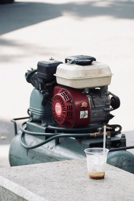
The worked example below uses a realistic small/medium facility stream: 2 m³/h average flow, 3,000 mg/L COD, 500 mg/L oil & grease, 80 mg/L NH₃-N. These are mid-range values for a compressor room with 3-5 reciprocating units and weekly blowdown.
- Characterize the stream. Average flow Q = 2 m³/h (peak 3-4 m³/h during blowdown). Influent COD = 3,000 mg/L; oil & grease = 500 mg/L; NH₃-N = 80 mg/L. Daily COD load = 2 m³/h × 24 h × 3,000 mg/L = 144 kg COD/day raw.
- Apply DAF. A correctly sized DAF drops oil to <50 mg/L and removes 15-25% of the COD with the float. Post-DAF COD ≈ 2,400 mg/L; post-DAF daily load = 2 × 24 × 2,400 / 1,000 = 115 kg COD/day. The DAF must be sized for peak flow — for a 4 m³/h peak, a dissolved air flotation unit in the 4-6 m³/h range is appropriate.
- Choose applied organic loading. For oily condensate with residual TPH, hold to the conservative end of the 0.6-1.2 kg COD/m³·day range. Use 0.8 kg COD/m³·day as the design point. If load is driven directly: required working volume = 115 / 0.8 = 144 m³. That number exceeds the reactor size a 2 m³/h stream would normally justify and signals the design is being load-limited, not HRT-limited.
- Cross-check by HRT. At Q = 2 m³/h, 144 m³ gives HRT = 72 h — far above the 6-12 h norm for an MBBR. The reactor would be oversized on a hydraulic basis, which is the diagnostic signature of a load-limited biological stage. Two options exist: (a) accept the larger volume because the load truly demands it, or (b) reduce the load upstream through better equalization and a polish DAF to bring post-DAF COD closer to 1,800-2,000 mg/L.
- Refine to a realistic working number. With an equalization tank providing 12-24 h of buffering and a polish step that brings post-DAF COD to ~2,000 mg/L, daily load drops to 96 kg COD/day. At 0.6 kg COD/m³·day (conservative) and 8-10 h HRT, working volume = 2 × 10 = 20 m³, sized to a 4-5 m³/h peak aeration basin. This is the number a small/medium facility can defend in front of a review engineer: 20 m³ working volume, 40-50% HDPE carrier fill, 8-10 h HRT at average flow.
- Select carrier media. HDPE carriers with 500-800 m²/m³ specific surface area and a density of 0.95-0.98 g/cm³ are standard. Fill fraction 30-50% keeps the bed fluidized at the coarse-bubble aeration rates required for oily service. The MBBR sizing for edible oil wastewater article covers analogous high-oil carrier selection in more depth.
MBBR Design Parameters for Oily Condensate Service
Use the table below as the single reference for review questions on HRT, dissolved oxygen (DO), food-to-microorganism ratio (F/M), and carrier fill. F/M is expressed in kg COD applied per kg mixed liquor volatile suspended solids per day. Specific surface area is the protected biofilm area per cubic meter of carrier.
| Parameter | Design range (oily condensate service) | Source / rationale |
|---|---|---|
| HRT (oxic zone) | 8-12 h | Protects biofilm from hydrocarbon shock |
| DO (oxic zone) | 2-4 mg/L | Nitrification requires ≥2 mg/L; oil suppression above 4 mg/L |
| F/M | 0.10-0.2 kg COD/kg MLVSS·day | Conservative for residual TPH |
| Carrier fill | 30-50% | Higher fill = more area, harder fluidization |
| Specific surface area | 500-800 m²/m³ | HDPE standard; PU foam up to 3,000 m²/m³ but fouls |
| pH | 6.5-8.0 | Nitrifier optimum 7.5-8.0 |
| Temperature | 15-35 °C | Nitrification halts above 40 °C |
| KLa target | 0.6-1.2 kg O₂/kg COD removed | Coarse-bubble for carrier fluidization |
| Applied organic loading | 0.6-1.2 kg COD/m³·day | Conservative when residual TPH >50 mg/L |
High-surface-area HDPE (500-800 m²/m³) is the default for oily service; polyurethane (PU) foam carriers reach 2,500-3,000 m²/m³ and can handle 1.5-2.0 kg COD/m³·day, but PU fouls within weeks in oily feeds and is harder to clean in place. Aeration uses coarse-bubble diffusers sized for both oxygen transfer and carrier fluidization — fine-bubble diffusers clog in oily service. The 2025 MDPI A2O-MBBR work (S1) supports the anaerobic → anoxic → oxic MBBR integration when NH₃-N accompanies the COD, with stable effluent quality reported at lab scale. Compare the broader pattern in the factory white water MBBR sizing guide when sizing parallel reactor trains.
Pretreatment Chain: API Separator → DAF → Equalization → MBBR
The MBBR only performs if the upstream train strips free oil, breaks emulsions, and smooths batch flow. The sequence below is the minimum viable chain for a compressor room discharge:
- API oil/water separator — removes free oil (≥100 µm droplets) by gravity; expects ≥90% free-oil removal and brings oil to 100-200 mg/L downstream.
- DAF — a dissolved air flotation unit with chemical conditioning drops emulsified oil to <50 mg/L and removes 15-25% of the COD with the float.
- Equalization tank — 12-24 h hydraulic retention; the single most important reactor for batchy condensate because it converts intermittent blowdown into a near-constant feed.
- pH adjustment — DAF effluent often sits at 6.0-6.5 from coagulant carryover; an automatic pH and coagulant dosing skid lifts the feed into the 6.5-8.0 window the MBBR requires.
- MBBR — oxic zone (or A2O train if ammonia is significant) sized per Section 3.
Sludge from the DAF float and the MBBR waste stream is routed to a sludge dewatering filter press in the 1-50 m² filter area range; expect 18-25% dry solids cake from the biological stream and 25-35% from the DAF float.
Validation, Startup, and Alarm Setpoints
A defensible MBBR spec is only defensible if the design numbers hold against real condensate. Run a 30-day bench test in a 50 L carrier-filled reactor on actual plant discharge before committing CAPEX; target >80% COD removal at the design HRT and F/M before scaling up. Seed the reactor with 10% v/v municipal activated sludge during the 3-6 week colonization period — bare HDPE carriers take 4-6 weeks to develop a robust biofilm, and seeding cuts that to 2-3 weeks. Critical alarm setpoints for the SCADA tag list: influent oil & grease >100 mg/L (indicates DAF breakthrough), reactor DO <1.5 mg/L (aeration failure or excess organic load), pH outside 6.0-8.5 (nitrifier collapse risk), and reactor temperature >40 °C (compressors in enclosed rooms can heat discharge streams in summer). The 2025 MDPI A2O-MBBR study (S1) reported stable effluent quality from a lab-scale integrated train across variable feed conditions — the same operating envelope an industrial A2O-MBBR should target once the pretreatment chain is locked in.
Frequently Asked Questions
What is the minimum pretreatment before an MBBR can treat compressor oily condensate?
Free oil must be removed by an API separator to <200 mg/L, then emulsified oil must be polished by a DAF to <50 mg/L oil & grease. Flow must be equalized over 12-24 h, and pH adjusted to 6.5-8.0. Without DAF, residual oil coats HDPE carriers and the biofilm sloughs within 2-4 weeks.
What HRT and applied organic loading should be used for an MBBR on oily condensate?
Design for 8-12 h HRT and 0.6-1.2 kg COD/m³·day applied organic loading, with the conservative 0.6 kg COD/m³·day end of the range when residual TPH exceeds 50 mg/L. Carrier fill is 30-50% HDPE at 500-800 m²/m³ specific surface area, and DO is held at 2-4 mg/L.
When should an A2O-MBBR be selected over a single-stage oxic MBBR for compressor condensate?
Select an anaerobic–anoxic–oxic MBBR (A2O-MBBR) when NH₃-N exceeds 50-80 mg/L alongside the COD load, or when discharge limits require simultaneous nitrification and carbon removal. The 2025 MDPI A2O-MBBR study (S1) confirmed stable effluent quality from this configuration at lab scale on high-strength recalcitrant organics.
How much working volume does a 2 m³/h, 3,000 mg/L COD condensate stream need in an MBBR?
After DAF drops oil to <50 mg/L and COD to ~2,000 mg/L, the post-DAF load is 96 kg COD/day. At 0.6 kg COD/m³·day applied loading and 8-10 h HRT, the MBBR working volume is approximately 20 m³ with 40-50% HDPE carrier fill. A load-driven calculation without equalization can give 140+ m³, which signals the design is load-limited and demands upstream buffering.