
Why Soapstock Water Breaks a Standard MBBR
Soapstock is the saponified layer skimmed from the caustic refining of vegetable oils — sodium salts of free fatty acids, entrained glycerides, and residual NaOH carried over from the refining centrifuge. Raw soapstock water enters a treatment plant at COD 15,000–50,000 mg/L, FOG 2,000–10,000 mg/L, pH 9–12, and 60–80 °C. Those four numbers together are what kill a generic MBBR design. Free oil coats the biofilm carrier within hours, the high pH suppresses nitrifying organisms and shifts the microbial community, and the heat strips biofilm from the media surface. The 2026 industry guidance is consistent: any MBBR pilot on this stream requires upstream oil separation before the biological step (S2, International Journal of Science and Research, 2017-12). A correctly sized MBBR will work on soapstock, but only behind a DAF, an equalization basin, pH correction, and cooling. The rest of this article walks the sizing math on that precondition, and the upstream train itself is detailed in the soapstock water pretreatment guide before MBR.
Step 1 — Characterize the Stream and Define the Effluent Target
Seven parameters have to land on the input sheet before any reactor volume is calculated, and all seven must come from a 24-hour composite sampler, not a grab: flow (m³/d), total and soluble COD, BOD₅, FOG, TSS, pH, and temperature. The soluble COD is the number that drives MBBR loading — total COD overstates the biodegradable fraction because it includes the emulsified oil fraction that DAF will remove. Define the effluent target next, because the loading calculation depends on the removal efficiency. A 2026 refinery reuse spec typically requires COD ≤ 150 mg/L for discharge and ≤ 50 mg/L for cooling-tower makeup, FOG ≤ 10 mg/L, and pH 6–9. Apply a peaking factor of 1.2–1.5× the average daily flow to the design flow so the reactor can absorb batch discharges from the refining hall. Anything measured on a grab sample is suspect — soapstock streams slug hard during soap-split campaigns and the composite is the only defensible basis for a tender.
| Parameter | Sampling | MBBR Sizing Role |
|---|---|---|
| Flow (m³/d) | 24-h composite + peak log | Sets hydraulic load and HRT window |
| Soluble COD (post-DAF) | Filtered 24-h composite | Drives OLR calculation in kg COD/m³·d |
| BOD₅ | 24-h composite | Confirms biodegradability; BOD/COD should be 0.4–0.6 |
| FOG (mg/L) | 24-h composite | Must be < 50 mg/L entering MBBR |
| TSS (mg/L) | 24-h composite | Should be < 100 mg/L after DAF to protect sieves |
| pH | Online probe | Target 6.7–7.5 inside the reactor (S2, 2017-12) |
| Temperature | Online probe | Target 15–35 °C; comfort band is 15–25 °C (S2, 2017-12) |
Step 2 — Pretreat Until the MBBR Sees a Soluble, pH-Neutral Feed
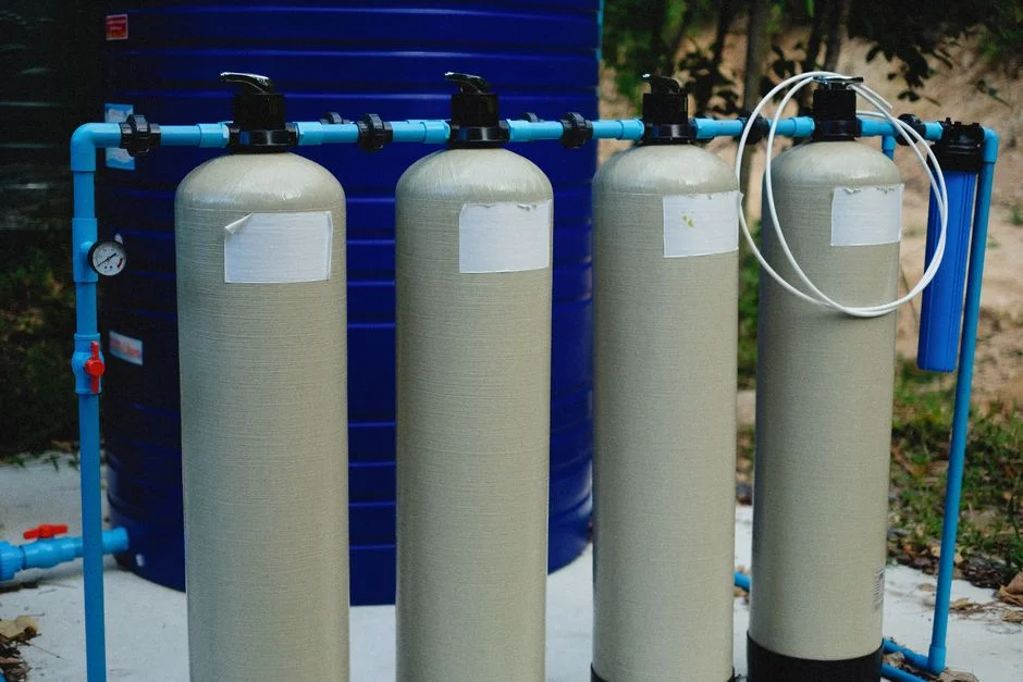
The MBBR sizing math is only valid when the feed entering the reactor is a soluble, pH-neutral, mesophilic stream. Four pretreatment steps get it there. DAF first — a dissolved air flotation system handles 4–300 m³/h and is the standard tool in food processing pre-treatment, targeting residual FOG < 50 mg/L into the equalization basin. Equalization follows, sized for 8–24 h HRT, with pH correction to 7.0–8.0 using CO₂ or H₂SO₄; avoid HCl because chloride pitting on stainless carriers is a real failure mode in this chemistry. Cooling is mandatory when the source exceeds 40 °C — drop to 25–35 °C before the MBBR so the biofilm stays attached; the 15–25 °C pilot window is the comfortable operating band cited in the literature (S2, 2017-12). Nutrient dosing rounds out the train: soapstock is often N-limited, so add urea and MAP (monoammonium phosphate) through an automatic chemical dosing skid if the COD:N:P ratio drifts above 100:5:1. Skipping any one of these four steps invalidates the loading rate you are about to pick.
Step 3 — Pick the Organic Loading Rate and HRT
Two numbers drive the entire reactor volume calculation: the organic loading rate (OLR) in kg COD per m³ of reactor per day, and the hydraulic retention time (HRT) in hours. For soapstock water after DAF, the design band is OLR 2–6 kg COD/m³·d; 2 is the conservative end for shock-loaded streams, 6 applies to steady-state food-grade discharges. The HRT follows from OLR: at OLR 2, HRT runs 18–24 h; at OLR 6, HRT compresses to 6–8 h. Outside that band removal efficiency drops sharply because the biofilm cannot metabolize fast enough at the low end and washout risk rises at the high end. The Kaldnes K1 carrier at 20% media fill is the conservative baseline reported in the academic literature (S1, Universitas Tanjungpura, 2017); for soapstock, push the fill to 30–40% to gain footprint without losing mixing, because the biodegradable fraction is high and the carrier is not the limiting surface. Cross-check the choice against a minimum 70% removal efficiency — anything below that and chemical precipitation or evaporation will beat biology on cost.
| OLR (kg COD/m³·d) | HRT (h) | Media Fill (%) | Application |
|---|---|---|---|
| 2 | 18–24 | 30 | Shock-loaded refinery, batch soapstock dumps |
| 4 | 10–14 | 30–40 | Mid-range design; suitable for most edible oil plants |
| 6 | 6–8 | 40 | Steady-state food-grade effluent, downstream MBR polish planned |
Step 4 — Calculate Reactor Volume, Media Volume, and Footprint
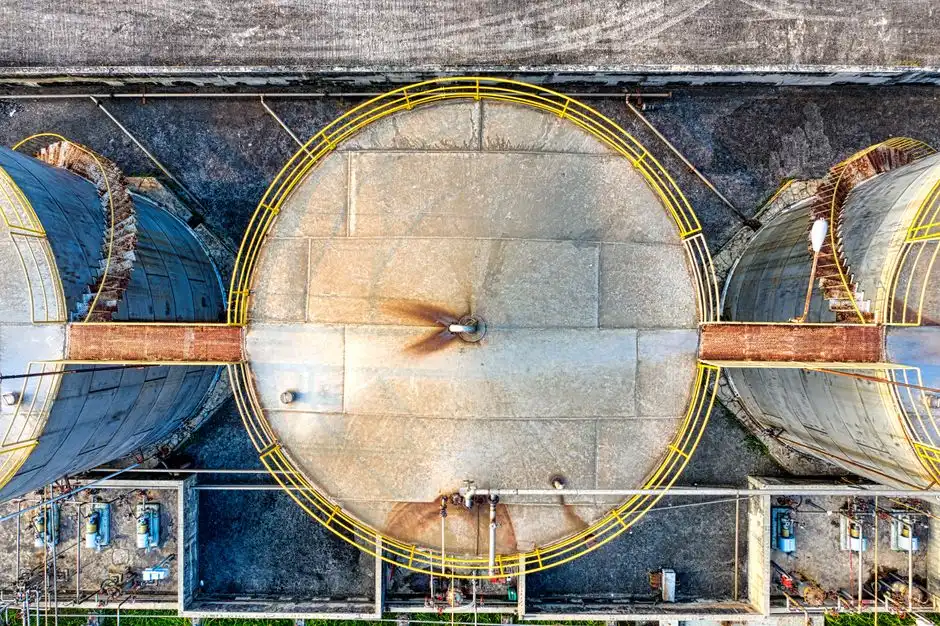
The sizing formulas are short and worth memorizing. Reactor volume V (m³) = Q (m³/d) × COD (kg/m³) ÷ OLR (kg COD/m³·d). Media volume = V × fill fraction. Worked through with 200 m³/d, post-DAF COD 8,000 mg/L, OLR 4, fill 30%: V = (200 × 8.0) / 4 = 400 m³; media volume = 400 × 0.30 = 120 m³; HRT = 400 / 200 = 2 days (48 h, deliberately cautious for a refinery with batch swings). Tank geometry: H:W ratio between 1:1 and 1.5:1, with a typical 5 m side-water depth, so a single reactor of 8 m × 10 m × 5 m SWD handles 400 m³. Use 3 mm wedge-wire cylindrical sieves on the outlet to retain Kaldnes-style carriers — wedge-wire outlasts perforated plate in this service. Footprint penalty versus a comparable conventional activated-sludge basin is real, on the order of 30–60% larger, but the trade is the absence of a sludge recycle loop and a separate clarifier; for a greenfield refinery, the MBBR layout often fits inside the same civil envelope as a CAS design once the clarifier and RAS pumps are removed.
Step 5 — Size the Aeration Blower and Mixing Air
Under-sized aeration is the single most common MBBR mistake. Two air streams have to be sized independently. Process air supplies the oxygen: budget 1.5–2.0 kg O₂ per kg COD removed, with an alpha-factor of 0.8 for the soapstock matrix, and design the DO setpoint at 4–5 mg/L consistent with pilot data (S2, 2017-12). Mixing air keeps the carriers in suspension: minimum 4–6 m³ of air per m² of tank area per hour, with 3 m³/m²·h as the absolute floor below which carriers settle and 8 m³/m²·h as the ceiling above which biofilm shears off the carrier surface. Blower selection: positive-displacement for variable-level service, multi-stage centrifugal for steady flows above 200 m³/d; discharge pressure typically 30–50 kPa to overcome water depth and sieve head-loss. On the instrumentation side, the three signals an operator actually uses are a DO probe on a PID loop to the blower, a pH probe tied to the acid dosing system, and a TSS probe on the effluent for early warning of biomass washout. A sizing logic that mirrors the same load-rationale used in sizing MBBR for machining coolant blowdown applies here as well — the blower governs the biology, not the other way around.
Worked Example — Sizing Sheet for a 150 m³/d Refinery
Inputs: Q = 150 m³/d, post-DAF soluble COD = 6,000 mg/L, FOG < 50 mg/L, pH 7.5, T 30 °C, effluent target COD ≤ 150 mg/L. Pick OLR = 4 kg COD/m³·d (mid-range, shock-tolerant). V_reactor = 150 × 6.0 / 4 = 225 m³. Media volume = 225 × 0.30 = 67.5 m³. HRT = 225 / 150 = 1.5 d = 36 h. Predicted effluent: COD 120–180 mg/L (97–98% removal), FOG < 10 mg/L, pH 7.0–7.5, suitable for direct discharge or for cooling-tower makeup after a downstream MBR polish. Aeration demand: 150 × 6.0 × 0.97 × 1.8 ≈ 1,570 kg O₂/d, requiring roughly 2,200 m³/h of process air at standard conditions, plus mixing air of 4 m³/m²·h over a 6 m × 7.5 m × 5 m SWD tank footprint (45 m² plan area × 4 = 180 m³/h). Total blower duty is on the order of 2,400 m³/h at 40 kPa, which a single 30 kW positive-displacement blower handles with margin. The table below is the deliverable.
| Item | Value | Unit |
|---|---|---|
| Design flow Q | 150 | m³/d |
| Post-DAF COD | 6,000 | mg/L |
| OLR | 4 | kg COD/m³·d |
| Reactor volume V | 225 | m³ |
| Media volume (30% fill) | 67.5 | m³ |
| HRT | 36 | h |
| Process air | ~2,200 | m³/h |
| Mixing air | ~180 | m³/h |
| Predicted effluent COD | 120–180 | mg/L |
Frequently Asked Questions
Can an MBBR handle raw soapstock without a DAF upstream?
No. Free oil coats the biofilm carrier within days, mass transfer collapses, and COD removal falls below 50%. DAF is not optional for this stream; the sizing math in this article assumes post-DAF soluble COD below 50 mg/L FOG.
MBBR versus MBR for soapstock water — when to pick which?
Use MBBR when the discharge target is COD around 150 mg/L and the plant does not need water reuse. Add an MBR polish after the MBBR when the target is sub-50 mg/L COD for cooling-tower makeup or boiler feed; the MBBR does the bulk load reduction cheaply and the MBR handles the suspended solids and residual organics.
What is the minimum dissolved oxygen for an MBBR on soapstock water?
Design for 4–5 mg/L DO at the outlet end of the reactor, consistent with pilot data (S2, 2017-12). Below 2 mg/L the biofilm sloughs, COD removal collapses, and carrier surfaces go anaerobic within hours.
How often do biofilm carriers need replacement?
Kaldnes-style carriers last 10+ years when FOG entering the MBBR stays below 50 mg/L and pH is held at 6.7–7.5. Budget 5–10% replacement per year as routine attrition rather than bulk failure.