
What Makes White Water a Distinct MBBR Design Case
White water from pulp/paper, textile, and food processing is not "industrial wastewater" in a generic sense — it is a hot, fibrous, surfactant-bearing stream that punishes conventional activated-sludge design. Typical white water runs at 40–60°C with TSS in the 300–1,500 mg/L range from fiber fines, COD of 800–3,000 mg/L, and pH that swings 4.5–9.0 across a production shift. The colloidal and surfactant load is what separates it from municipal sewage: laundry-style streams (the closest academic analog from the Tanjungpura University MBBR study, Kusuma et al.) carry carboxymethyl cellulose, calcium, phosphate, silicate, and bleach, and that same surfactant profile shows up in textile and de-inking wash water. That same study showed MBBR with 20% Kaldnes K1 fill reduced COD, BOD, phosphate, and surfactant simultaneously — proof the biofilm route handles colloidal surfactant load when sized properly. A conventional activated-sludge or low-rate trickling filter approach cannot tolerate the temperature swing, the fiber blinding of clarifier weirs, or the foam events that follow a pH excursion. MBBR's protected surface area and biofilm robustness make it the default biology once the influent is characterized and pretreated correctly.
Step 1 — Characterize the White Water Influent
Every defensible MBBR sizing begins with influent data, not assumed defaults. Pull a 7-day composite across all production shifts, not a single grab — white water variability is the single largest source of under-sized reactors in the field. The minimum parameter set is: flow (m³/day) with a peak factor of 1.5–2.0×, COD, BOD₅, TSS, temperature, pH, and surfactant or oil/grease where applicable. The published low-strength benchmark from the Spain MBBR work cited in the IJSR review (Calderón, 2012) is influent COD of 120–150 mg/L at 5–15 hr HRT; the China fixed-media submerged biofilter data (Chundong, 2012) reports COD 270–300 mg/L, NH₄-N 30–35 mg/L, TN 35–40 mg/L at 1.5 hr HRT. White water typically runs 5–20× stronger than those reference points, which is why single grab samples routinely under-size MBBRs by 30–50% — composite sampling captures the wet-end, broke, and wash-down peaks that drive the real load. A 2 mm rotary bar screen installed upstream of the sampling point protects the auto-sampler from rag and fiber fouling — see the engineering notes on a rotary bar screen for fiber and rag removal for typical aperture sizing.
| Parameter | Typical White Water Range | Low-Strength MBBR Reference (Spain, Calderón 2012) | Fixed-Media Reference (China, Chundong 2012) |
|---|---|---|---|
| COD (mg/L) | 800–3,000 | 120–150 | 270–300 |
| BOD₅ (mg/L) | 300–1,200 | — | — |
| TSS (mg/L) | 300–1,500 | — | — |
| Temperature (°C) | 40–60 | ambient | ambient |
| pH | 4.5–9.0 | neutral | neutral |
| Surfactant / FOG | 25–200 mg/L (textile/food) | low | low |
Step 2 — Calculate the Organic Load and Pick the Volumetric Loading Rate
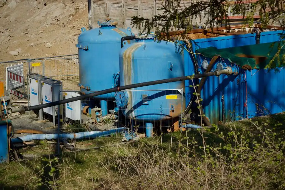
Convert the composite data into a daily load: Organic load (kg COD/day) = Q (m³/day) × COD (kg/m³). For a 500 m³/day stream at 2,000 mg/L COD, the load is 500 × 2.0 = 1,000 kg COD/day. The target volumetric organic loading rate (VLR) for white water MBBR is 0.5–2.5 kg COD/m³·day, with 1.0–1.5 as a conservative middle band that leaves headroom for the peak factor and seasonal swings documented in Step 1. Reactor working volume (m³) = load ÷ VLR, so 1,000 kg COD/day ÷ 1.25 = 800 m³ of working volume. If the discharge permit also covers ammonia or total nitrogen, cross-check the BOD-loading equivalent — at 800 mg/L BOD the same stream carries 400 kg BOD/day, and nitrification MBBRs typically run at 0.05–0.15 kg NH₄-N/m³·day. Documenting both COD and BOD loadings in the design basis gives the permitting authority a defensible calculation path; the same approach is used in our related guide on sizing MBBR for machining coolant blowdown, where surfactant-bearing streams dominate the load profile.
Step 3 — Select Media Fill Fraction and Carrier Type
Media fill is the lever that controls effective surface area inside the reactor without changing the civil footprint. The 20% Kaldnes K1 fill used in the Tanjungpura laundry study is a proven lower bound for COD/BOD/surfactant reduction; in practice, white water reactors run 20–40% fill. Higher fill (30–40%) increases protected surface area — typically 500–1,200 m²/m³ depending on carrier geometry — but raises mixing energy and head loss across the screens. For HDPE carriers the operating density is 0.95–0.98 g/cm³, just under water, which keeps them suspended with proper aeration or mechanical mixing. The trade-off is real: a 40% fill can deliver 30–50% more treatment capacity in the same volume, but only if the aeration system can supply the mixing energy without stripping biofilm. For fiber-laden white water, avoid carriers with small apertures or unprotected slots; specify protected surface area media (cylindrical K1, K3, or equivalent) so fiber strands cannot wedge into the biofilm and blind the carrier. Geometry matters more than brand — the IJSR review on MBBR for river water notes that carrier shape and protected area are the primary drivers of treatment efficiency, not the polymer formulation.
Step 4 — Set HRT, Confirm Hydraulic Capacity, and Size Aeration

Target HRT for white water MBBR after DAF is 6–12 hours, anchored against the Spain MBBR range of 5–15 hr (Calderón, 2012) and the China hybrid MBBR at 12 hr cited in the IJSR review. Verify the reactor volume against both Step 2 and the hydraulic check: V (m³) = Q (m³/hr) × HRT (hr). For 500 m³/day at 8 hr HRT, the hydraulic volume is 500/24 × 8 = 167 m³ per cell — the Step 2 working volume of 800 m³ therefore requires multiple cells in series (or parallel) to honor both the loading-driven and HRT-driven sizing. Dissolved oxygen setpoint is 2.0–3.0 mg/L in aerobic cells, with design aeration at 0.2–0.4 Nm³ air per m³ reactor volume per hour for white water BOD loadings. Temperature correction is not optional: white water at 35–55°C reduces oxygen transfer efficiency, and the alpha factor for clean water to process water conversion typically falls in the 0.7–0.85 range — apply it in the blower sizing or the cells will run anoxic under peak load. Aeration also serves as mixing energy to keep the media fluidized; undersized blowers cause media settling and dead zones.
| Parameter | Design Value (White Water MBBR) | Lower Bound / Source | Upper Bound / Source |
|---|---|---|---|
| HRT | 6–12 hr | 5 hr (Spain, Calderón 2012) | 15 hr (Spain); 12 hr (China hybrid MBBR) |
| VLR (kg COD/m³·day) | 0.5–2.5 | 0.5 (conservative) | 2.5 (peak-tolerant design) |
| Media fill (%) | 20–40 | 20% (Tanjungpura K1 study) | 40% (high-rate, energy-costed) |
| DO setpoint (mg/L) | 2.0–3.0 | 2.0 (heterotrophic limit) | 3.0 (nitrification margin) |
| Aeration (Nm³ air/m³·hr) | 0.2–0.4 | 0.2 (low-load cells) | 0.4 (high-load, high-T cells) |
| Alpha factor (T correction) | 0.7–0.85 | 0.7 (45–55°C, high TDS) | 0.85 (35–40°C) |
| Protected surface area (m²/m³) | 500–1,200 | 500 (large K1) | 1,200 (small protected media) |
Step 5 — Specify Pretreatment So the MBBR Performs
Most field failures blamed on MBBR are pretreatment failures. The minimum upstream train for white water is: coarse screening to <5 mm, then fine screening to <2 mm via a rotary bar screen to remove fiber, rags, and plastics that would otherwise blind the media. Dissolved air flotation follows, dropping TSS below 100 mg/L and stripping colloidal surfactant and FOG before they coat the biofilm — see the operating envelope of a DAF system for white water TSS removal for typical air-to-solids ratios. pH adjustment to 6.5–8.0 via an automatic pH adjustment system is mandatory for surfactant-bearing streams, since pH excursions outside that window collapse nitrification and can strip biofilm. An equalization basin sized for 8–24 hr of peak flow dampens the load swings that would otherwise push the MBBR beyond its VLR band; academic MBBR reviews consistently flag equalization as essential for stable operation under variable industrial loads. The same logic appears in our guide to paper machine seal water pretreatment before MBBR, where fiber and temperature control drive the upstream unit selection.
MBBR vs MBR vs DAF for White Water — When to Choose Each
Technology choice is driven by effluent quality, footprint, and reuse intent. MBBR is the right answer when the discharge destination is a sewer or surface water and the permit allows conventional secondary limits — it tolerates load swings, has no membrane to foul, and is simpler to operate. MBR (submerged PVDF) is the right answer when the plant needs reuse-quality effluent, has a tight footprint, or faces strict TSS/BOD limits — an MBR system for reuse-quality white water effluent delivers <1 μm filtration and stable TSS below 5 mg/L. DAF is a pretreatment tool, not a standalone solution for high-BOD white water — it removes floatables, colloids, and emulsified FOG, but not dissolved BOD. The decision rule an EPC can defend in front of procurement: discharge to sewer → MBBR; reuse or tight limits → MBR; high oil/FOG only → DAF pretreatment + downstream biology.
| Technology | Best Fit | Effluent BOD/COD | Effluent TSS | Footprint | Key Risk |
|---|---|---|---|---|---|
| MBBR | Sewer or surface water discharge | BOD ≤ 30 mg/L, COD ≤ 200 mg/L (typical) | 20–80 mg/L (with DAF upstream) | Moderate | Media fouling if pretreatment lapses |
| MBR | Reuse, tight permit, small footprint | BOD ≤ 5 mg/L, COD ≤ 50 mg/L | < 5 mg/L | Compact | Membrane fouling, CIP cost |
| DAF (alone) | High FOG / TSS removal as pretreatment | Marginal dissolved BOD removal | < 100 mg/L (with coagulant) | Small | Cannot meet secondary BOD limits alone |
Worked Sizing Example: 500 m³/day White Water Plant
Inputs: Q = 500 m³/day, COD = 2,000 mg/L (2.0 kg/m³), BOD = 800 mg/L, TSS = 600 mg/L, T = 45°C, pH 7.5. Daily COD load = 500 × 2.0 = 1,000 kg COD/day. At a conservative VLR of 1.25 kg COD/m³·day, reactor working volume = 1,000 / 1.25 = 800 m³. Configure as two cells in series, 400 m³ each, with 30% Kaldnes-type media fill and an HRT of 8 hr per cell (Q/24 × 8 = 167 m³ per cell minimum; 400 m³ gives margin). Aeration: 0.3 Nm³ air/m³·hr × 800 m³ = 240 Nm³/hr, with the blower sized using an alpha factor of 0.8 for the 45°C operating temperature. Effluent target for sewer discharge: COD ≤ 200 mg/L, BOD ≤ 30 mg/L, which represents >90% COD removal and is consistent with the >85% reductions reported for MBBR on surfactant-bearing streams in the academic literature. For plants facing tighter reuse limits, swapping the second cell for an MBR membrane module converts the train into a hybrid MBBR-MBR system without changing the upstream biology.
Frequently Asked Questions
What VLR should I use to size an MBBR for white water?
Use 0.5–2.5 kg COD/m³·day, with 1.0–1.5 as a defensible middle band for composite-sampled white water. The lower end suits high-temperature, high-TSS streams with surfactant; the upper end applies to pretreated, equalized streams with peak factors already absorbed in the design basis.
What media fill fraction works best for fibrous white water?
Run 20–40% fill with protected surface area HDPE carriers (Kaldnes K1, K3, or equivalent). The 20% Kaldnes K1 fill used in the Tanjungpura study is a proven lower bound for surfactant and COD reduction; higher fills increase capacity but require proportional mixing energy.
What HRT range applies to white water MBBR design?
Target 6–12 hours after DAF pretreatment, bracketed against the 5–15 hr range reported in the Spain MBBR study (Calderón, 2012) and the 12 hr hybrid MBBR reported in the IJSR review. Cells below 5 hr risk COD breakthrough on surfactant peaks; cells above 12 hr consume footprint without treatment gain.
Why does MBBR fail on white water in the field?
Almost always pretreatment failure: fiber blinding the media, FOG coating the biofilm, or pH excursions outside 6.5–8.0. Adding coarse and fine screening, DAF, and automatic pH adjustment upstream resolves the majority of field failure modes documented in pulp and paper MBBR audits.