Why Copper Concentrator Water Breaks a Default MBR Design
Standard municipal MBR sizing assumes dissolved Cu below 0.05 mg/L, negligible heavy-metal fouling, and a stable BOD/NH₃-N load — assumptions that collapse the moment a copper concentrator feed enters the bioreactor. Thickener overflow, flotation filtrate, and tailings decant typically carry dissolved Cu, Zn, Pb, Cd, suspended fines, and process reagents (xanthate, guar, sulfide depressants) in concentrations that disrupt nitrification, fragment flocs, and accelerate trans-membrane pressure (TMP) rise. Field data from A/O-MBR studies on metal-laden water show realistic influent bands of 0.25–2.56 mg/L for low-strength streams and 3.7–32.3 mg/L for high-strength streams across Zn, Cu, Pb, and Cd (Feng et al., 2013, as reviewed in Water, Air, & Soil Pollution, 2025).
Free Cu²⁺ above approximately 1–2 mg/L is biocidal to nitrifiers and weakens floc-forming bacteria, so biological kinetics, F/M ratios, and SRT targets cannot be copied from municipal curves. The fouling mode also shifts: metal-hydroxide colloids and fine mineral particles form a low-permeability cake layer that drives TMP faster than domestic-waste MBRs experience. Floc-size data confirms the problem — mean floc size of 209.31 μm in a conventional MBR dropped 22% to 163.19 μm in an A/O-MBR treating the same wastewater with metal co-precipitates, and smaller flocs are well documented to foul tighter (Hwang et al., 2007, as cited in the same review). Any 2026 design that borrows municipal flux, HRT, or MLSS defaults will under-size the cassette hall and over-promise membrane life.
Step 1 — Characterize Influent Before Any Sizing
Every defensible MBR sizing calculation starts with a characterization matrix that the tender reviewer can audit line by line. Pull 24-h composite samples across at least one full operating week, and measure flow (m³/h or m³/day), pH, total suspended solids (TSS), total dissolved solids (TDS), COD, BOD₅, ammonia-nitrogen, and dissolved Cu, Zn, Pb, Cd by ICP-MS. Cu speciation matters: dissolved Cu²⁺ behaves differently from Cu-cyanide (Cu(CN)₃²⁻) and Cu-ammine (Cu(NH₃)₄²⁺) complexes generated in flotation circuits, and each species demands a different pretreatment train.
Document variability — peak flow factor, diurnal Cu load swings, and mill shutdown/startup transients — because shock loads drive the contingency factor carried into the bioreactor volume. Lock the discharge or reuse target before opening a sizing spreadsheet: <0.5 mg/L Cu for surface discharge under typical EPA mining effluent guidelines, or tighter limits for milling-circuit reuse, sets the required biological polishing and any post-MBR RO stage. Finally, flag toxicity indicators: free Cu²⁺ > 1 mg/L is a hard signal that precipitation must precede the biological stage, not follow it.
Step 2 — Pretreatment Trains That Protect the MBR
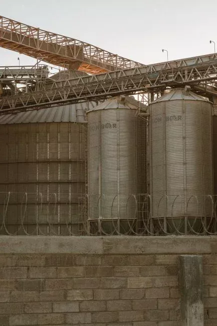
The MBR is the most expensive unit operation in the train, so the pretreatment line must remove everything that destroys membrane life. Start with equalization and pH conditioning to 8.5–9.5 to drive alkaline precipitation of Cu(OH)₂ (Ksp ≈ 2.2 × 10⁻²⁰), then send the stream through coagulation-flocculation and a clarifier to drop TSS below approximately 50 mg/L before the membranes. For flotation and thickener overflows, a dissolved air flotation system handles oil and fine suspended solids effectively, while a lamella clarifier is better suited to higher-solids tailings decant streams.
Heavy-metal polishing follows: ion exchange (chelating resin) or sulfide precipitation (Na₂S or FeS) pulls dissolved Cu from 1–5 mg/L down to <1 mg/L, the threshold at which nitrifier activity recovers. If Cu-cyanide complexes are present, alkaline chlorination at pH > 10.5 destroys CN⁻ ahead of biology to protect biomass and meet downstream limits. A multi-media filter then acts as the final guard before the MBR cassette, stripping residual grit and precipitated solids that would otherwise score the membrane surface. The full pretreatment scope — equalization through multimedia filtration — is laid out in the heap leach bleed pretreatment before MBR guide and the smelter scrubber blowdown pretreatment before MBR spec guide, both of which share the same upstream logic.
Step 3 — Biological Stage Sizing (Aerobic MBR for Cu-Bearing Water)
The aerobic MBR tank is sized to give biomass enough residence time to recover between Cu pulses while still polishing BOD and nitrifying ammonia. Use F/M ratio 0.08–0.15 kg BOD/kg MLSS·day — lower than the 0.15–0.25 range typical of municipal MBRs — so the biomass has slack to rebound from metal shocks. Hold MLSS at 8,000–12,000 mg/L: high enough to bind dissolved Cu onto extra-polymeric substances and provide shock absorption, low enough to keep mixed liquor viscosity below roughly 5 cP and avoid pumping penalties.
HRT should land at 18–30 hours at design flow, and SRT at 25–40 days to retain slow-growing, more Cu-tolerant nitrifier populations. Hold dissolved oxygen at 2.0–3.0 mg/L with coarse-bubble aeration; in a submerged MBR, that same aeration sustains sludge in suspension and scours the membrane surface, so it is doing three jobs at once (Besha et al., 2017; Drioli & Giorno, 2010, as reviewed in Water, Air, & Soil Pollution, 2025). Assume 22 ± 1 °C aerobic MBR temperature unless site data dictates otherwise (Wu et al., 2008 in the same review). For aeration sizing, actual oxygen demand ≈ 1.2–1.5 × (BOD removed + 4.6 × NH₃-N nitrified), with a 10–15% Cu-induced stress factor on top to cover endogenous respiration lift under metal exposure.
Step 4 — Membrane Module Selection and Flux Derating
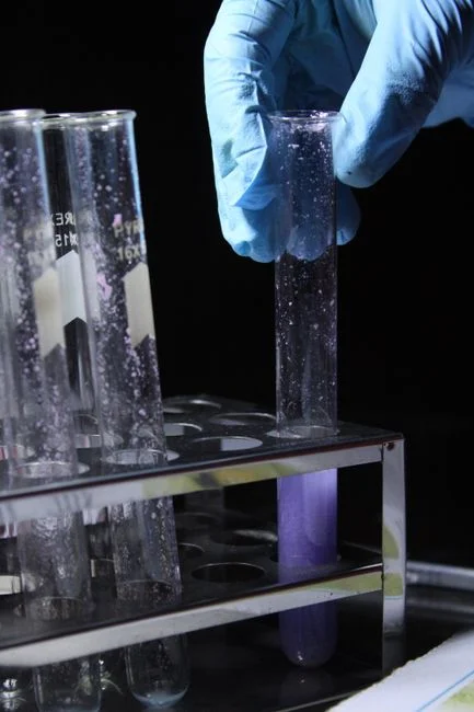
Select 0.1 μm PVDF flat-sheet submerged modules for copper concentrator duty — the geometry tolerates the metal-hydroxide cake better than hollow fibers and is easier to clean chemically on site. The DF series PVDF flat-sheet MBR module ships in 80–225 m² cassettes rated at 32–135 m³/day each, which fits most mining plant scales. Flat-sheet membranes cannot rely on active backwashing the way hollow fibers can (Le-Clech et al., 2006, as cited in the 2025 MBR fouling review), so the operating recipe must be built around relaxation cycles and periodic chemical clean-in-place (CIP).
Municipal design flux of 0.8–1.2 m³/m²/day must be derated to 0.4–0.6 m³/m²/day on copper-bearing water to manage the metal-hydroxide cake layer and the 22% floc-size reduction documented for A/O-MBR metal feeds. Use the 3-min relaxation / 5-min backwash cycle as the baseline operating protocol (Wu et al., 2008) and design separate process-aeration and membrane-scour blower trains. Aeration intensity for membrane scour should land at 80–120 m³ air per m² membrane area per hour in the cassette zone.
| Parameter | Municipal MBR | Cu Concentrator MBR | Basis |
|---|---|---|---|
| Design flux (m³/m²/day) | 0.8–1.2 | 0.4–0.6 | Metal-hydroxide cake; smaller flocs |
| MLSS (mg/L) | 8,000–12,000 | 8,000–12,000 | Viscosity vs. Cu-binding balance |
| HRT (h) | 4–8 | 18–30 | Cu-shock recovery + nitrification |
| SRT (days) | 15–25 | 25–40 | Retain Cu-tolerant nitrifiers |
| F/M (kg BOD/kg MLSS·d) | 0.15–0.25 | 0.08–0.15 | Lower loading for shock buffer |
| Relaxation / backwash (min) | 2 / 3 | 3 / 5 | Wu et al. 2008 protocol |
| Membrane scour (m³ air/m²·h) | 40–80 | 80–120 | Tighter cake layer offset |
Step 5 — Compute Membrane Area and Cassette Count
Membrane area follows the closed-form A_m = Q_design / J_net, with J_net pulled from the derated 0.4–0.6 m³/m²/day band and Q_design at peak hourly flow (not average daily flow). For a worked example, take Q = 500 m³/day and J_net = 0.5 m³/m²/day: A_m = 1,000 m². That size loads into 5 × DF-225 cassettes at 200 m² each (5 × 200 = 1,000 m²), and adding 20% contingency for Cu-shock events rounds up to 6 cassettes at 1,200 m² of installed membrane.
Reactor volume from V = Q × HRT = 500 m³/day × 1.0 day = 500 m³; carry 25% contingency for Cu-shock hold-up, which rounds the tank to 625 m³. Check the MLSS inventory: 625 m³ × 10,000 mg/L = 6,250 kg MLSS, comfortably within wasting capacity for an SRT of 30 days (wasting rate ≈ 208 kg MLSS/day). Cross-check the duty against an integrated MBR membrane bioreactor system skid capacity range of 10–2,000 m³/day; at 500 m³/day, a single integrated skid or a parallel two-skid layout both fit within the catalog envelope. For broader context on alternative bioreactor geometries, the MBR vs MBBR comparison for industrial plants walks through when a moving-bed design can substitute, though it sacrifices the absolute effluent clarity an MBR delivers for membrane-cassette polishing.
Operating, Cleaning, and Contingency Practices
Set the 3-min relaxation / 5-min backwash cycle as the operating baseline; escalate to chemical clean-in-place when TMP rises 30% above the clean-water baseline. Schedule maintenance cleans with sodium hypochlorite at 500–1,000 mg/L free chlorine every 1–2 weeks, and run a citric-acid soak (1–2% w/w) every 2–4 weeks to dissolve metal-scale deposits that hypochlorite cannot touch. The DF series' individually replaceable elements let the operator swap a fouled cassette without taking the whole train offline, which matters during a Cu-shock event.
Install online Cu monitoring on the influent; if free Cu²⁺ exceeds 5 mg/L, trigger partial bypass to equalization to protect biomass until the precipitation stage recovers. Plan 20–30% membrane area contingency in the cassette hall to absorb future Cu load creep or stricter discharge limits — a cassette slot left empty at commissioning is cheaper than a plant shutdown to retrofit later. A consolidated sizing summary that the design engineer can paste directly into a datasheet is shown below.
| Parameter | Value (500 m³/day example) | Notes |
|---|---|---|
| Influent Cu target to biology | < 1 mg/L | After precipitation + IX/sulfide |
| MLSS | 10,000 mg/L | 8,000–12,000 mg/L band |
| HRT | 1.0 day (24 h) | 18–30 h band |
| SRT | 30 days | 25–40 day band |
| F/M | 0.10 kg BOD/kg MLSS·d | 0.08–0.15 band |
| Net flux | 0.5 m³/m²/day | 0.4–0.6 derated band |
| Membrane area (gross) | 1,000 m² | Q ÷ J_net |
| Cassettes (DF-225, 200 m² each) | 5 + 1 contingency = 6 | 20% area contingency |
| Reactor volume (gross) | 625 m³ | 25% volume contingency |
| Membrane scour air | 80–120 m³/m²·h | Coarse-bubble cassette zone |
Frequently Asked Questions
What dissolved Cu²⁺ concentration is toxic to MBR biomass?
Free Cu²⁺ above approximately 1–2 mg/L is biocidal to nitrifiers and weakens floc-forming bacteria in conventional activated sludge and MBR systems. The design target after pretreatment is therefore < 1 mg/L dissolved Cu entering the bioreactor, achieved through alkaline precipitation to pH 8.5–9.5 followed by ion exchange or sulfide polishing.
What membrane flux should be used for an MBR on copper concentrator water?
Derate the design flux from the municipal 0.8–1.2 m³/m²/day band down to 0.4–0.6 m³/m²/day on copper-bearing water. The reduction manages the metal-hydroxide cake layer and the documented 22% floc-size drop in A/O-MBR metal feeds, which together accelerate TMP rise if municipal flux is held.
How do you calculate membrane area for a copper concentrator MBR?
Membrane area A_m = Q_design ÷ J_net, where J_net is pulled from the derated 0.4–0.6 m³/m²/day range. For Q = 500 m³/day and J_net = 0.5 m³/m²/day, A_m = 1,000 m², which loads as 5 × DF-225 cassettes with one contingency cassette for 20% area margin.
What pretreatment is required before an MBR treating copper process water?
The required pretreatment chain is equalization and pH conditioning to 8.5–9.5, coagulation-flocculation, dissolved air flotation or lamella clarification, ion exchange or sulfide precipitation for Cu polishing, alkaline chlorination if Cu-cyanide complexes are present, and multimedia filtration as a final guard ahead of the membrane cassette.
Related Equipment
- automatic chemical dosing system — specifications, capacity range, and technical data