Why copper concentrator water is a DAF sizing problem of its own
Thickener overflow re-entering the process-water dam is the most common reason a copper concentrator commissions a dissolved air flotation system — and it is the worst stream to size against a municipal DAF textbook. Two distinct feeds drive the design: thickener overflow at 50–500 m³/h with 200–2,000 mg/L TSS at pH 7–11, and tailings reclaim or process-water return at 1,000–20,000 mg/L TSS carrying residual xanthate, frother (MIBC, pine oil), and lime residues. Feed source controls both the hydraulic and chemical envelope, so a single recycle percentage or surface loading will not transfer between the two.
The governing physics are well established: per CRC Press chapter S3 on floc size and density, particles below ~10 μm and flocs with bulk density near that of water govern whether DAF outperforms sedimentation. Copper concentrator feed is dominated by 1–50 μm gangue silica, reagent-coated copper sulfides, and precipitated hydroxides — a population that sits squarely in the DAF-favorable window. Bubble-particle attachment is reliable, but only after flocculation, because raw mineral fines are too small and too close to neutral buoyancy to be captured by a bubble alone. DAF is preferred over sedimentation for these streams because rise rates of 5–15 m/h outperform gravity settling when solids density is 1.2–2.6 g/cm³ but particle diameter is sub-50 μm.
The three governing parameters every DAF sizing starts from
Every defensible DAF sizing for a copper mill starts with three locked numbers: hydraulic surface loading rate (SLR), air-to-solids (A/S) ratio, and recycle rate. SLR is the design flow divided by the effective flotation area; conventional DAF operates at 5–15 m/h, and high-rate units run 20–40 m/h. For reagent-coated fines in thickener overflow, stay at the lower end of the conventional band (8–12 m/h). For polished clarified water or low-TSS reclaim, push toward 15 m/h. The A/S ratio — grams of dissolved air delivered per gram of influent solids — has a 0.005–0.060 design window across the industry, but copper concentrator overflow should target 0.02–0.06 g/g because feed TSS swings diurnally with mill campaigns. Recycle rate ties directly to A/S: at 4–6 bar saturator pressure, an 8–20% recycle is typical, with 10–15% as the standard band and 15–20% reserved for heavy sulfide slurries where A/S must be held at 0.04–0.06 g/g even at peak TSS.
| Parameter | Conventional DAF | High-rate DAF | Copper concentrator target |
|---|---|---|---|
| Hydraulic SLR (m/h) | 5–15 | 20–40 | 8–12 (overflow), 12–15 (reclaim) |
| A/S ratio (g air/g solids) | 0.005–0.060 | 0.010–0.040 | 0.02–0.06 |
| Recycle rate (% of Q) | 8–20 | 5–12 | 10–15 standard, 15–20 heavy sulfide |
| Saturator pressure (bar) | 4–6 | 5–7 | 4–6 |
| Floc size target (μm) | >10 | >10 | >10 (per CRC Press S3) |
These three parameters are coupled, not independent. Raising recycle from 10% to 15% at constant saturator pressure raises dissolved air delivery by 50% without changing the geometry — a useful lever when TSS rises but the flotation cell is already built. The reverse is also true: if the recycle pump is undersized, no increase in saturator pressure will rescue the A/S ratio on a peak-TSS day. Build the design from A/S first, then size recycle to match.
Step-by-step DAF sizing for a 200 m³/h thickener overflow
This is the worked example you can scale to your own Q and TSS. The feed: 200 m³/h of thickener overflow at 1,000 mg/L TSS, pH 8.5, with residual xanthate and frother carryover.
Step 1 — Confirm Q and TSS, compute solids load. Solids load = 200 m³/h × 1,000 g/m³ = 200,000 g/h = 200 kg/h. Confirm with a 24-hour composite; diurnal swings in copper mill thickener discharge routinely hit ±30%.
Step 2 — Pick SLR and size the flotation area. With reagent-coated fine gangue, choose a conservative 10 m/h (mid-range, defensible at design review). Required flotation area = 200 m³/h ÷ 10 m/h = 20 m². A standard rectangular tank 4 m wide × 5 m long × 2.5 m SWD gives exactly 20 m²; include a 0.5 m freeboard for froth. If peak Q is 250 m³/h, the same tank runs at 12.5 m/h and remains inside the 5–15 m/h band.
Step 3 — Pick A/S and size the recycle. Target A/S of 0.03 g/g for nominal TSS. Air required = 200 kg/h × 0.03 = 6 kg air/h. At 5 bar saturator pressure, water holds roughly 21 mg/L of dissolved nitrogen plus oxygen; a 12% recycle at 200 m³/h feed = 24 m³/h recycle, delivering approximately 7 kg/h of releasable air. That clears the 6 kg/h target with ~15% margin. If TSS rises to 1,500 mg/L, solids load climbs to 300 kg/h and air demand rises to 9 kg/h — at that point the engineer should either raise recycle to 15% or accept a higher A/S of 0.03 g/g on a richer feed.
Step 4 — Specify flocculation to hit >10 μm flocs. Per CRC Press S3, floc size must exceed 10 μm for reliable bubble attachment. Specify a 5-minute flocculation HRT (≈ 17 m³ for 200 m³/h) with anionic polyacrylamide at 1.5 mg/L and PAC at 50 mg/L, dosed through an automatic chemical dosing system with flow-paced control.
| Step | Input | Equation / Assumption | Result |
|---|---|---|---|
| 1. Solids load | Q = 200 m³/h, TSS = 1,000 mg/L | Q × TSS | 200 kg/h |
| 2. Flotation area | SLR = 10 m/h | Q ÷ SLR | 20 m² (4 m × 5 m) |
| 3. Air required | A/S = 0.03 g/g | Solids × A/S | 6 kg air/h |
| 3. Recycle | 12% at 5 bar | 0.12 × Q × 21 mg/L × η_release | ~7 kg/h delivered |
| 4. Flocculation | PAM 1.5 mg/L, PAC 50 mg/L, 5 min HRT | Target >10 μm | 17 m³ floc tank |
Reagent and flocculation envelope for copper flotation waters
The standard reagent train for copper concentrator water is pH adjust → coagulant → flocculant → flocculation tank → DAF. pH adjust uses lime or sulfuric acid to hold 7–9, which keeps residual copper in the particulate form rather than redissolving it. Coagulant dose is 20–100 mg/L of PAC (polyaluminum chloride) or alum; in copper circuits PAC is preferred because it works across the 7–9 pH band without re-liming. Flocculant is anionic polyacrylamide at 0.5–3 mg/L, prepared through an automatic chemical dosing system at 0.05–0.1% active solution and dosed inline just ahead of the flocculation tank. Flocculation HRT of 5–10 minutes is the design window; below 3 minutes flocs are weak, above 15 minutes they shear.
Anionic PAM is preferred over cationic for mineral slurries because cationic polymer reacts with residual xanthate to form insoluble gummy complexes that blind the saturator and destabilize the float blanket downstream. The single most common commissioning failure on copper mill DAF retrofits is overdosing PAC: 200+ mg/L drives fine calcium-aluminate flocs that pass through the floc tank, blind the nozzle, and reduce air delivery by 30–50% within hours. Specify the upper dose as 100 mg/L with a low-level alarm at 80 mg/L; if the surface water does not clarify at that dose, the upstream problem is feed solids, not coagulant.
Pretreatment, integration, and where DAF fits in the flowsheet
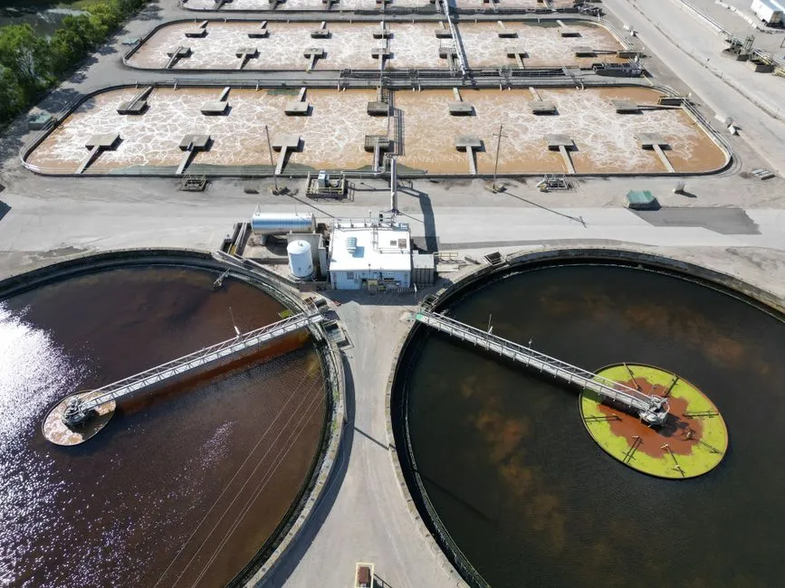
DAF cannot do the headworks job on its own, and it does not finish the job on the back end. Ahead of the flotation cell, install a rotary mechanical bar screen with 6–10 mm openings to remove rags, wood chips, and tramp from thickener overflow lines; without it, rag fouling of the recycle nozzles is a weekly maintenance event. If TSS exceeds 3,000 mg/L, or if the DAF must remain in standby for one cell-wash per week, put a lamella clarifier in parallel as a polishing step rather than as a primary — the lamella handles bulk settling and the DAF handles the fine, low-density fraction that the lamella cannot.
Downstream, DAF does not remove dissolved copper. For dissolved-metal compliance, pH/sulfide precipitation, ion exchange, or RO must follow — see our related guidance on heap leach bleed pretreatment before MBR and smelter scrubber blowdown pretreatment before MBR for the downstream trains. The DAF's job is to drop TSS and free oil to a level the downstream unit can tolerate, and to do it with a 15-minute residence rather than an 8-hour clarifier.
Sizing checklist and common pitfalls
Before the RFQ goes out, run the following QA on the design basis. Each line is something a copper mill DAF retrofit has missed at least once.
| # | Checklist item | Design value | Acceptable range |
|---|---|---|---|
| 1 | Peak Q with 25% margin | m³/h | +25% over 24-h peak |
| 2 | Peak TSS | mg/L | 1.5× design TSS |
| 3 | A/S ratio at peak TSS | g/g | 0.02–0.06 |
| 4 | Recycle % at peak Q | % | 10–15 standard, 15–20 heavy sulfide |
| 5 | Saturator pressure | bar | 4–6 |
| 6 | Flocculation HRT | min | 5–10 |
| 7 | Scraper torque | Nm | Per floated solids mass |
| 8 | Sludge handling capacity (to plate and frame filter press) | kg DS/h | ≥ 1.2× design solids load |
Three pitfalls recur across copper mill DAF retrofits. Undersizing the recycle pump starves the cell of whitewater; the unit looks like it is under-performing when it is actually air-limited, and operators respond by raising coagulant, which makes the saturator blind. Over-aerating (saturator above 6 bar, recycle above 20%) drives fine bubbles that trap frother and lift a wet, unstable float blanket that collapses back into the cell. Ignoring diurnal flow swings from the mill is the third: the DAF is sized on the 12-hour average and then chokes on the morning shift when the mill ramps up; the design Q should be the rolling 4-hour peak, not the daily mean. For mills that swing widely, also review our notes on sizing a DAF for white water discharges.
Frequently Asked Questions
What A/S ratio should I use for copper thickener overflow?
Target 0.02–0.06 g of dissolved air per gram of influent solids. For thickener overflow at 200–2,000 mg/L TSS, 0.03 g/g is a defensible design point; size the recycle pump to deliver 10–15% of Q at 4–6 bar saturator pressure. On heavy sulfide slurries above 2,000 mg/L, push to 15–20% recycle to keep A/S at 0.04–0.06 g/g.
What hydraulic surface loading rate applies to copper concentrator water?
Use 8–12 m/h for reagent-coated fines in thickener overflow, and 12–15 m/h for clarified or low-TSS reclaim. The flotation area equals design flow divided by the chosen SLR; a 200 m³/h overflow at 10 m/h requires 20 m². Conventional DAF units operate at 5–15 m/h, while high-rate designs can reach 20–40 m/h but need lamella or parallel plate internals.
Which flocculant works for xanthate-bearing flotation water?
Anionic polyacrylamide at 0.5–3 mg/L. Cationic PAM reacts with residual xanthate to form insoluble complexes that blind the saturator and destabilize the float blanket. Pair anionic PAM with 20–100 mg/L of PAC as the coagulant, hold pH at 7–9, and target 5–10 minutes of flocculation HRT to produce flocs larger than 10 μm.