
Why Desizing Effluent Is a Distinct DAF Sizing Problem
Sizing a DAF for desizing effluent requires matching hydraulic loading, air-to-solids ratio, and micro-bubble contact to the stream's PVA, starch, and lubricant load. For textile wash water with COD 500–1,200 mg/L and TSS 2,000–10,000 mg/L, design hydraulic loading of 5–15 m/h, recycle ratio 20–40%, and A/S 0.01–0.04, then verify with jar tests at process temperature (60–95°C).
Desizing is the wash-off of sizing agents — PVA, modified starch, CMC, or acrylate blends — from woven fabric before dyeing and finishing. These agents make the stream behave differently than generic textile effluent. PVA and modified starch are highly hydrophilic and generate very high COD and BOD with a low nutrient ratio (COD:N often above 20:1), which limits downstream biological polishing without nutrient dosing (per the textile wash-water envelope in the Comprehensive review of industrial wastewater treatment techniques, PMC, 2024). The same envelope sets TSS in the 2,000–10,000 mg/L range and dissolved solids at 300–1,000 mg/L — that is the load window a desizing DAF must be sized against, not a generic textile average.
Temperature is the second variable that breaks generic guidance. Desizing wash boxes run at 60–95°C. Above 70°C, dissolved air solubility drops, floc strength weakens, and polymer conformation shifts, so bench data collected at 25°C over-predicts performance by 15–30% on A/S. A DAF sized like a cold-side oil-removal unit — 15 m/h loading, A/S 0.02, no temperature compensation in the saturator — will underperform on desizing, making stream-specific sizing mandatory from the first equation onward.
Step 1 — Characterize the Desizing Flow and Loads
A defensible influent dataset is required before applying any sizing equation. The minimum inputs are average and peak flow (m³/h), influent TSS, COD, BOD, temperature, pH, and the size agent type and concentration (PVA, starch, CMC, or blend). For blended lines, capture the ratio — a 70/30 PVA/starch mix behaves differently from pure starch, and the polymer window shifts accordingly.
Peak factor for batch desizing ranges from 1.2–1.5× average, with hot wash surges up to 2× when multiple wash boxes discharge in step. Treat the 2× surge as your design peak, not your average — the saturator and contact zone must ride through it without bubble collapse. Typical loads fall inside the textile wash-water envelope: TSS 2,000–10,000 mg/L, COD 500–1,200 mg/L, moderate-to-high BOD, and dissolved solids 300–1,000 mg/L (PMC, 2024). PVA-dominant lines skew toward the upper TSS and COD bounds; starch-dominant lines trend lower on COD but generate higher suspended starch colloids.
Sample at the desizing bath overflow, not at the combined plant outfall. Desizing peaks are short (15–45 min) and get diluted by the rest of the mill in a 24-h composite, so a plant-outfall sample under-reports peak TSS by 40–60%. Use a 24-h composite paired with 4–6 grab samples across the wash-box cycle to capture the peak envelope.
Step 2 — Select Hydraulic Loading and Surface Area
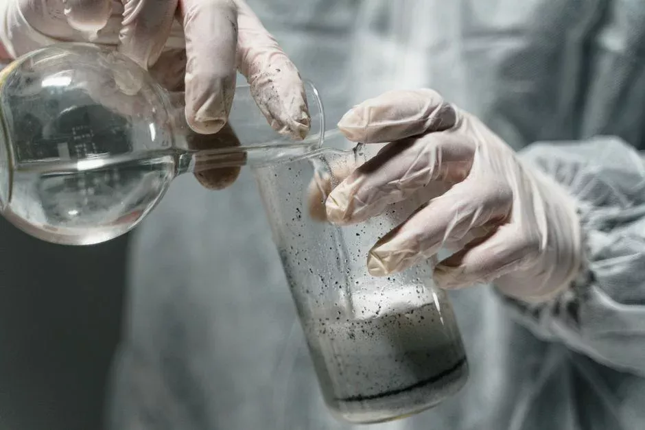
The design envelope for desizing DAF is 5–15 m/h surface loading. Use the lower end (5–8 m/h) for hot, high-PVA streams above 70°C, and the upper end (10–15 m/h) for cooler starch-only streams. The sizing equation is: required effective flotation area A = Q_peak / hydraulic loading rate. For a 50 m³/h peak at 8 m/h, A = 6.25 m².
Multiply that result by 1.2–1.5 to cover TSS surges, foaming, and polymer carryover — the real-world operating margin not provided by jar data. On a 50 m³/h peak at 8 m/h with a 1.3× factor, the design effective area becomes 8.1 m², which rounds to a standard 9–10 m² flotation cell. The DAF system covers standard surface areas across the 4–300 m³/h range, so the 50 m³/h case maps to a mid-range cell without custom tankage.
If footprint is tight, add a lamella pack inside the DAF. Lamella plates push effective hydraulic loading to 20–40 m/h on cool streams, though on hot desizing effluent above 70°C you should derate that to 15–25 m/h because floc strength drops. The lamella-assisted DAF reference design is the bench to scale from when footprint, not flow, is the constraint.
Step 3 — Set Recycle Ratio, Saturator Pressure, and Air-to-Solids
Recycle ratio for textile desizing DAFs sits in the 20–40% band, with 25–30% the common operating point. The saturator runs at 4–6 bar, with retention time ≥60 s. Below 60 s, micro-bubbles collapse before they reach the contact zone, causing a 20–40% loss of available bubble surface area.
Air-to-solids (A/S) is the design variable that determines whether flotation works. Target A/S 0.01–0.04 on a mass basis: the lower end for coarse, dense flocs (large starch granules, well-flocculated PVA), the upper end for fine colloidal PVA that needs more bubble attachment events per unit mass. The physics behind this is set out in The Role of Floc Size and Density in Dissolved Air Flotation and Sedimentation (CRC Press, 2024) — floc size and bubble–particle attachment density govern removal efficiency, not bubble count alone. A saturator delivering 30 µm bubbles at the right A/S will outperform one delivering 10 µm bubbles at the wrong ratio.
At 70–90°C, compensate by increasing saturator pressure by ~0.5 bar (to 4.5–6.5 bar) to maintain dissolved-air mass, or accept a lower A/S and derate expected TSS removal by 10–15%. Accurate A/S also depends on reliable coagulant and polymer feed, so pair the saturator with a controllable automatic chemical dosing skid — a dosing pump drifting ±10% will swing the A/S ratio off target without showing up on the saturator gauge.
Step 4 — Coagulation, Flocculation, and Polymer Window
Run jar tests at the actual desizing bath temperature, not at 25°C lab ambient. A dose sweep of 5, 10, 15, 20, 25, 30 mg/L cationic or nonionic flocculant, paired with 50–150 mg/L coagulant (PAC or ferric chloride dosed ahead of the flocculant), defines the operating window. The typical dose window for desizing is 5–25 mg/L flocculant, with starch-dominant lines on the lower end and PVA-dominant lines on the upper end.
Target a 0.5–2 mm floc. Below 0.5 mm, the bubble cannot lift the floc reliably, resulting in partial removal with turbid subnatant. Above 2 mm, the floc settles before the bubble attaches. Over-dosing polymer creates a stable emulsion that defeats DAF entirely, with a visible milky subnatant and floating polymer skins. Dose to the minimum that breaks the emulsion, not the maximum that forms a visible floe. The same automatic chemical dosing skid referenced in Step 3 carries both the coagulant and flocculant streams, with separate pulse channels to keep the dose ratios stable across peak load.
DAF Sizing Parameter Summary for Desizing Effluent
The table below packages the sizing logic into a datasheet row for a 50 m³/h desizing line. Hydraulic loading and A/S ranges come from peer-reviewed DAF design practice; influent chemistry bounds come from the textile wash-water envelope in the PMC industrial wastewater review (2024).
| Parameter | Design Value (50 m³/h desizing line) | Typical Range |
|---|---|---|
| Design flow (average) | 30 m³/h | 20–40 m³/h |
| Peak flow | 50 m³/h (1.67× avg) | 1.2–2.0× average |
| Influent TSS | 5,000 mg/L | 2,000–10,000 mg/L |
| Influent COD | 900 mg/L | 500–1,200 mg/L |
| Temperature | 80°C | 60–95°C |
| Hydraulic loading | 8 m/h | 5–15 m/h |
| Effective flotation area | 6.25 m² (8.1 m² with 1.3× margin) | — |
| Recycle ratio | 30% | 20–40% |
| Saturator pressure | 5 bar (4.5–6.5 bar hot) | 4–6 bar |
| Saturator retention | ≥60 s | 60–120 s |
| Air-to-solids (A/S) | 0.025 | 0.01–0.04 |
| Coagulant (PAC) dose | 100 mg/L | 50–150 mg/L |
| Flocculant (CPAM) dose | 15 mg/L | 5–25 mg/L |
| Expected TSS removal | 85–92% | 80–95% |
| Expected COD removal | 40–55% | 35–60% |
Common Sizing Mistakes on Desizing Streams
Using 25°C jar test data to size a 70–90°C desizing DAF is a costly error. Floc strength drops with temperature, and the A/S and polymer dose must be re-validated hot — otherwise the unit ships with a saturator pressure that cannot dissolve enough air and a polymer dose that breaks the emulsion at room temperature but fails at process temperature. The second mistake is undersizing the saturator: without ≥60 s retention at 4–6 bar, micro-bubbles collapse before contacting floc, and removal drops 20–40% without a visible mechanical fault.
The third mistake is ignoring downstream sludge. High-PVA floc is gelatinous and dewaters poorly; under-sizing the sludge train creates a bottleneck that backs up the DAF float blanket. Pair the DAF with a plate-and-frame sludge dewatering press sized for 18–25% dry solids in the cake, not the 30%+ typical of biological sludge. If your line also runs a white-water or print/dye train, the sizing logic differs — see the guides on sizing a DAF for white water discharges and treating printing and dyeing wastewater for those streams.
Frequently Asked Questions
What hydraulic loading should I use for a hot PVA desizing DAF?
Use 5–15 m/h, with the lower end (5–8 m/h) for high-PVA streams above 70°C. Hot PVA floc is weaker and needs more contact time, so
Frequently Asked Questions
What hydraulic loading should I use for a hot PVA desizing DAF?
Apply a hydraulic loading rate of 3–6 m³/m²/h for hot PVA desizing effluent to provide sufficient residence time for the flotation of low-density polymer flocs. If the influent temperature exceeds 50°C, reduce the loading to 3–4 m³/m²/h and confirm that tank materials are rated for thermal stress, as elevated temperatures decrease dissolved air solubility and can reduce microbubble release efficiency by up to 20%.
Can one DAF handle both desizing and combined textile wastewater?
Using a single DAF for mixed streams is technically challenging