Why Soapstock Water Needs a Purpose-Built DAF
A DAF for edible-oil soapstock water is sized by first quantifying the flow (m³/h) and the soap-oil-and-grease (SOG) mass load (kg/h), then selecting a hydraulic loading rate of 5–10 m/h and an air-to-solid ratio of 0.02–0.06 to define the contact-zone surface area, and finally verifying recycle ratio (20–50%) and saturator pressure (4–6 bar) to deliver 10–80 µm micro-bubbles. This sequence reliably removes 80–95% of FOG and 60–90% of TSS from soapstock effluent.
Soapstock water is the aqueous phase generated during edible-oil refining, neutralization, and acid-splitting of soapstock. It carries free oil, emulsified oil, saponified fatty acids, glycerol, and dissolved COD loadings that routinely fall between 5,000 and 25,000 mg/L (per S1 academic findings on industrial mineral-oil effluents and S3 soap-factory DAF data). Free oil rises in a conventional API separator, but the bulk of the load in 2026 is emulsified droplets below 20 µm and saponified FOG with near-neutral buoyancy. Parallel-plate interceptors and corrugated plate packs do not capture these species reliably because the residence time required to float sub-20 µm droplets exceeds 2 hours — economically unworkable in a 4–300 m³/h packaged DAF envelope.
The 2026 design band that consistently drives continuous DAF selection across edible-oil refineries, oleochemical plants, and integrated soap factories is: flow 4–300 m³/h, SOG 1,000–5,000 mg/L, COD 5,000–25,000 mg/L, and TSS 500–3,000 mg/L. Continuous DAF with pressurized saturation, micro-bubble attachment, and a flocculation stage is the standard primary step because the alternative — equalization, chemical heating, and gravity — typically delivers under 40% SOG removal (S3, 1980 soap-factory study). S1 reinforces this by documenting that pilot and full-scale DAF work on the same SOG/COD envelope achieves >80% oil removal only when the air-to-solid ratio and recycle are explicitly designed rather than left to vendor defaults.
Step 1 — Characterize the Soapstock Stream
Defensible DAF sizing starts with a structured characterization sheet, not a flow number. The minimum data set an EPC reviewer will accept is: average and peak flow (m³/h), temperature (°C), pH, SOG and FOG (mg/L), COD and BOD₅ (mg/L), TSS (mg/L), TDS (mg/L), and surfactant load (mg/L as MBAS or LAS). A peak-to-average ratio above 1.5 should be flagged, because a 30-minute soapstock discharge from a batch refining line can transiently push SOG above 6,000 mg/L.
Sampling protocol must match the discharge pattern. Soapstock flow is batch-driven: a 24-hour composite plus three 8-hour grab samples across a refining campaign captures both the steady inter-batch drip and the periodic slug from a split-soapstock pump-out. Without this, the SOG mass load is typically underestimated by 30–50%, which propagates into an undersized saturator and under-dosed chemistry.
Temperature is a sizing constraint, not just a process note. Hot soapstock at 50–70 °C reduces viscosity and improves oil release from the matrix, but a saturator fed above 40 °C loses air solubility — Henry's constant degrades roughly 30% between 25 °C and 50 °C at 5 bar. The practical fix is an equalization/cooling step that brings the saturator feed to 30–40 °C, which keeps the micro-bubble flux in its design band. pH matters just as much: acid-split soapstock at pH 2–4 converts soap to free fatty acids that float readily, but the H₂S risk and the corrosion envelope demand SS316L or FRP-lined internals rather than standard SS304. Specify this in the data sheet; the cost delta is small compared with a six-month unplanned shutdown from pitting.
Step 2 — Calculate the FOG Mass Load and Target Removal
The FOG mass load is the single number that drives every downstream calculation. The formula is straightforward:
FOG mass load (kg/h) = Q (m³/h) × SOG (mg/L) × 10⁻³
Worked at design conditions: 50 m³/h × 2,000 mg/L × 10⁻³ = 100 kg/h SOG to be removed. That is the rate at which the saturator must deliver air, the flocculation tank must grow floc, and the skimming mechanism must remove float. Expressing load in kg/h rather than mg/L forces the engineer to think about absolute capacity — which is what fails during peak hours, not the average concentration.
The 2026 target envelope for a properly specified DAF on soapstock is 80–95% SOG removal and 60–90% TSS removal (per S1 DAF optimization data). The wide range is intentional: an acid-split stream with pH 3, 55 °C, and 2,000 mg/L SOG typically lands at 90–95% removal with PAC + APAM dosing, while a neutralized caustic stream with emulsified soap can drop to 75–85% without polyacrylamide. Residual load defines the downstream train: a 90% removal of 100 kg/h SOG leaves 10 kg/h for the MBR polishing step, well within its 50–200 mg/L SOG handling envelope.
Two side calculations are worth doing in parallel. First, the float yield — kg of skimmings per kg of SOG removed — is typically 1.05–1.20 in 2026 field data, because the float carries flocculant, entrained water, and TSS. Second, the sludge volume to the plate-and-frame filter press: 10–25% of inlet SOG mass reaches the press as float, which sets the press capacity. A 50 m³/h, 2,000 mg/L SOG stream generates roughly 250–500 kg/d of float solids, a load a 1–10 m² plate-and-frame press can handle on a single shift.
Step 3 — Size the Contact Zone by Hydraulic Loading Rate
Hydraulic loading rate (HLR) is the primary sizing equation for the DAF tank surface area, defined as volumetric flow divided by the contact-zone footprint. The 2026 design band for soapstock DAF is 5–10 m/h: the lower end (4–6 m/h) for high-SOG streams above 3,000 mg/L or for sites with variable loading, the upper end (8–10 m/h) for polishing duty on already-pretreated streams. Most packaged DAF units in the 4–300 m³/h envelope are quoted at 6–8 m/h because that range balances footprint and removal performance.
The formula and a worked number:
A (m²) = Q (m³/h) ÷ HLR (m/h)
At 50 m³/h and HLR 8 m/h, A = 6.25 m². A 20% safety margin for peak flow and under-performing chemistry pushes this to 7.5 m². Translated into a footprint: 3.0 m × 2.5 m contact zone with a 2.0–2.5 m side-water depth gives 15–18.75 m³ of effective contact volume, which corresponds to 18–22 minutes of hydraulic retention. Twenty to forty minutes is the working envelope for the contact zone in 2026 — under 15 minutes and the floc does not equilibrate with bubbles; over 40 minutes and the tank is paying for capital that the recycle ratio should provide.
Tank geometry is a footprint decision rather than a performance one. Rectangular contact zones are standard in 4–300 m³/h packaged DAF units because they integrate cleanly with the saturator, recycle pump, and skimmer on a single skid; circular tanks appear in larger custom builds above 300 m³/h where concrete construction dominates. The HydropureWater packaged DAF family covers 13 standard models across this 4–300 m³/h range, which is why rectangular geometry remains the practical default for 2026 refinery bids.
Step 4 — Set the Air-to-Solid Ratio and Recycle
Air-to-solid (A/S) ratio is the mass of dissolved air supplied per mass of suspended and buoyant solids, with units of kg air per kg SOG+TSS. The 2026 design band is 0.02–0.06. Soapstock with high emulsified FOG sits at the higher end, around 0.04–0.06, because the bubble demand is set by the surface area of oil droplets that must be lifted, not just by the bulk mass. Under-sizing the A/S ratio is the single most common reason a DAF bid removes only 60% SOG instead of the 90% the vendor claimed.
Worked at design conditions: 100 kg/h SOG × 0.05 A/S = 5 kg/h air required. At 25 °C and 5 bar saturator pressure, approximately 25 g of air dissolves per m³ of water (i.e., 0.025 kg/m³). The recycle flow needed to deliver 5 kg/h is 5 ÷ 0.025 = 200 m³/h, which is a 400% recycle on a 50 m³/h forward flow. That figure is the saturation limit; in practice, a standard 2026 packaged DAF runs 20–50% recycle (10–20 m³/h on a 50 m³/h forward flow) and relies on the contact-zone mixing to deliver the necessary bubble flux. The saturator-only calculation above is a check: if your design demands more than 50% recycle to hit the A/S target, the contact zone is too small or the chemistry is under-dosed.
The envelope for 2026 packaged DAF is 20–50% recycle; higher recycle is justified only when SOG exceeds 3,000 mg/L, when temperature exceeds 40 °C, or when the saturator runs below 4 bar. S4 documents the underlying mechanism: floc size and density — not bubble size alone — control attachment efficiency. A flocculation retention of 5–15 minutes before the contact zone must be preserved; a flash mix of 30–60 seconds is not enough for anionic polyacrylamide to grow a strong, low-density floc that bubbles can lift. If a vendor proposes cutting the floc tank to save footprint, the A/S and HLR are meaningless.
Step 5 — Specify the Saturator and Micro-Bubble Generator
The saturator datasheet line is where most cheap DAF bids are exposed. A 2026 saturator for soapstock service runs 4–6 bar(g), with 5 bar as the food-processing default. Below 4 bar, dissolved-air concentration falls below 20 g/m³ and the A/S target cannot be met at standard recycle. Above 6 bar, the energy penalty rises faster than the marginal air flux, and the saturator retention becomes excessive.
Micro-bubble diameter should be specified explicitly, not as "dissolved air." The target band is 10–80 µm, with 30–50 µm median for FOG flotation. Bubbles below 30 µm rise too slowly to scavenge the full oil population; bubbles above 80 µm have low surface-area-to-volume and burst at the float blanket. Specify by nozzle or educter type — a 2026 saturator with a properly designed eductor array typically produces 25–40 µm bubbles at 5 bar, while a poorly designed one produces a wide 10–120 µm distribution. The retention in the saturator at design pressure is 30–90 seconds; below 30 seconds the water does not reach 85% saturation, and the air flux the engineer calculated in Step 4 is never delivered.
Material selection is the final saturator line. SS304 is adequate for streams below 50 °C at neutral pH. For acid-split soapstock at pH 2–4, SS316L or FRP-lined carbon steel is required to avoid pitting at the air-water interface. A dissolved air flotation system integrates saturator, recycle pump, contact zone, and skimmer into one skid with the material specified for the application — which is why most 2026 refinery bids anchor on a packaged unit rather than a custom build.
Step 6 — Select Coagulant and Flocculant Chemistry
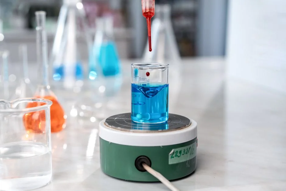
The A/S ratio and HLR only work when the chemistry is correct. The 2026 dosing envelope for soapstock DAF has four lines: pH adjustment to 6.5–8.0 with NaOH or H₂SO₄ (acid-split soapstock must be raised from pH 2–4 before the floc tank), coagulant at 50–200 mg/L PAC (polyaluminum chloride) or 100–300 mg/L FeCl₃ to neutralize the emulsified oil charge, and flocculant at 1–5 mg/L anionic polyacrylamide (APAM, 10–18 mol% charge, MW 10–18 MDa) to grow a strong, low-density floc.
Charge neutralization and floc growth are sequential, not simultaneous. PAC or FeCl₃ destabilizes the oil-in-water emulsion by compressing the electrical double layer; APAM then bridges the destabilized droplets into a 0.5–3 mm floc with effective density below 0.95 g/cm³ — light enough for a 30–50 µm bubble to lift. S4 confirms that floc density and size are the dominant DAF performance variables: get the chemistry wrong, and no amount of saturator pressure compensates.
Dose control should be PLC-driven, not manual. Online pH and a streaming-current meter (SCM) feeding back to the coagulant pump hold the dose within ±10% of setpoint across a feed stream that swings 2× over a shift. A skid-mounted automatic chemical dosing system sized for the 50 m³/h reference case has a footprint under 2 m² and handles PAC, APAM, NaOH, and H₂SO₄ from a single panel — a defensible line item in any 2026 EPC bid.
Step 7 — Integrate the DAF With Downstream Polishing
DAF effluent typically leaves 50–200 mg/L SOG and 100–300 mg/L COD — too high for direct discharge but right in the operating window of a submerged MBR. A 2026 standard configuration for edible-oil refineries is DAF → equalization → submerged MBR system with PVDF flat-sheet membranes at 0.1 µm nominal pore size, which drives residual COD below 500 mg/L and residual oil below 10 mg/L. MBR hydraulic retention is 6–10 hours, mixed liquor suspended solids 8,000–12,000 mg/L, and the membrane air-scour demand is met by the recycle blower already specified for the DAF saturator where practical.
Final polishing depends on the discharge permit. For a plant with surface-water discharge, the MBR effluent is sufficient. For an inland plant with a zero-discharge permit, RO follows the MBR to bring conductivity below 200 µS/cm, with a brine stream sent to an evaporation/crystallization ZLD step. Both options are well-documented in the 2026 edible-oil refinery design literature, and both assume the DAF has done the heavy lifting on FOG and TSS.
Skimmings from the DAF are the other integration point. Float mass is 10–25% of inlet SOG (per the 2026 mass-balance envelope), and the float is a high-oil, high-solids sludge that a plate-and-frame filter press handles cleanly at 1–500 m² filtration area, 6–8 bar filtration pressure, and a cake solids target of 30–40%. A 50 m³/h, 2,000 mg/L SOG stream produces roughly 250–500 kg/d of float solids, which a 5 m² press dewater in a single shift cycle. The filtrate returns to the DAF inlet; the cake goes to fat rendering or incineration depending on the site.
Master Sizing Parameter Table for 2026 DAF on Soapstock Water
The table below consolidates every parameter from the seven steps into a single, auditable reference. Each row maps back to a numbered step so the datasheet is traceable to a calculation.
| Parameter | Design Range | Unit | 2026 Soapstock Typical | Step |
|---|---|---|---|---|
| Flow envelope | 4–300 | m³/h | 50–150 | 1 |
| SOG influent | 1,000–5,000 | mg/L | 2,000 | 1, 2 |
| COD influent | 5,000–25,000 | mg/L | 10,000 | 1, 2 |
| TSS influent | 500–3,000 | mg/L | 1,200 | 1, 2 |
| Temperature | 30–70 | °C | 55 (cooled to 35 at saturator) | 1, 5 |
| pH | 2–10 (adjusted to 6.5–8.0) | — | 3 → 7 | 1, 6 |
| Hydraulic loading rate | 5–10 | m/h | 8 | 3 |
| Contact-zone retention | 20–40 | min | 22 | 3 |
| Air-to-solid ratio | 0.02–0.06 | kg air / kg SOG+TSS | 0.05 | 4 |
| Recycle ratio | 20–50 | % of forward flow | 30–40 | 4 |
| Saturator pressure | 4–6 | bar(g) | 5 | 5 |
| Saturator retention | 30–90 | s | 60 | 5 |
| Micro-bubble diameter | 10–80 | µm | 30–50 median | 5 |
| Flocculation retention | 5–15 | min | 10 | 4, 6 |
| PAC dose | 50–200 | mg/L | 100 | 6 |
| APAM dose | 1–5 | mg/L | 2 | 6 |
| SOG removal | 80–95 | % | 90 | 2, 7 |
| TSS removal | 60–90 | % | 80 | 2, 7 |
| DAF effluent SOG | 50–200 | mg/L | 100 | 7 |
The packaged DAF family covers 13 standard models across the 4–300 m³/h envelope, with a 50 m³/h unit at HLR 8 m/h mapping to a 7.5 m² contact zone and a 5 bar saturator. For a defensible 2026 datasheet, anchor the bid on this dissolved air flotation system specification rather than a generic "DAF unit."
Worked Example: 50 m³/h, 2,000 mg/L SOG Soapstock Stream
Inputs: Q = 50 m³/h, SOG = 2,000 mg/L, COD = 10,000 mg/L, T = 55 °C (cooled to 35 °C at the saturator), pH = 3 (acid-split soapstock, raised to 7.0 with NaOH before the floc tank).
Step 2 — mass load: 50 × 2,000 × 10⁻³ = 100 kg/h SOG to be removed.
Step 3 — contact zone: HLR 8 m/h → A = 50 ÷ 8 = 6.25 m², rounded to 7.5 m² with a 20% safety margin. Footprint 3.0 m × 2.5 m, side-water depth 2.2 m, effective contact volume ~16.5 m³, retention ~20 minutes.
Step 4 — air and recycle: A/S 0.05 → 5 kg/h air. At 5 bar and 25 g/m³ solubility, the saturator-only recycle would be 200 m³/h (400%) — but a standard packaged DAF runs 30–40% recycle (15–20 m³/h) and delivers the required flux through proper contact-zone mixing. Specify 18 m³/h recycle (36%) as the design point.
Step 5 — saturator: 5 bar(g), 60-second retention, SS316L vessel, eductor array specified for 30–50 µm bubble median.
Step 6 — chemistry: NaOH to pH 7.0 (dose ~150 mg/L), 100 mg/L PAC, 2 mg/L APAM, 10-minute flocculation retention in a dedicated tank with paddle speed 30–60 rpm.
Step 7 — integration: DAF skimmings to a 5 m² plate-and-frame filter press; DAF effluent to a submerged MBR with PVDF flat-sheet membranes, then RO for water reuse. Expected DAF outlet: 100 mg/L SOG, 800 mg/L COD, 240 mg/L TSS — comfortably inside the MBR envelope.
Final selection: Packaged DAF rated for 50 m³/h with a 5 bar saturator, SS316L wetted parts, 36% recycle, integrated floc tank, and PLC-controlled dosing. Mass balance: 100 kg/h SOG in, 10 kg/h SOG to MBR, 90 kg/h SOG to skimmings, 250–500 kg/d float to filter press.
Frequently Asked Questions
What hydraulic loading rate should I use for a high-SOG soapstock stream?
For SOG above 3,000 mg/L or variable feed, target 4–6 m/h to give the contact zone enough time to scavenge emulsified oil. For polishing duty on a pretreated stream, 8–10 m/h is acceptable. Most 2026 packaged DAF units in the 4–300 m³/h envelope are quoted at 6–8 m/h as the working midpoint.
How do I size the recycle pump if the saturator is rated at 5 bar?
At 5 bar and 25 °C, dissolved-air concentration is approximately 25 g/m³. Multiply the required air mass (kg/h, from A/S ratio × SOG mass load) by 40 to get the recycle flow in m³/h at the saturation limit. In practice, packaged DAF units run 20–50% recycle and rely on contact-zone mixing to deliver the design flux.
Can a DAF handle acid-split soapstock at pH 2–4?
Yes, with SS316L or FRP-lined wetted parts and a 5 bar saturator. Adjust the pH to 6.5–8.0 with NaOH before the floc tank to avoid H₂S release and to optimize coagulant performance. The 2026 design band explicitly covers pH 2–10 influent corrected to neutral at the DAF inlet.
What removal efficiency should I expect for a properly sized DAF on soapstock?
Expect 80–95% SOG removal and 60–90% TSS removal when HLR, A/S, recycle, and chemistry are all in spec. Below 80% SOG removal, the most common causes are under-sized saturator, under-dosed APAM, or saturator feed above 40 °C. For an end-to-end process train, see the edible-oil soapstock water pretreatment before MBR process guide.
How does a soapstock DAF compare with a paint-booth DAF in sizing?
Both follow the same HLR and A/S framework, but soapstock runs lower HLR (5–8 m/h vs 8–12 m/h for paint booth) because the oil droplets are more emulsified and the float blanket is heavier. A side-by-side comparison is given in the DAF sizing guide for paint booth curtain water.