

What API Mother Liquor Actually Is
API mother liquor is the clarified aqueous overflow leaving a corrugated-plate API oil-water separator — not raw refinery wastewater and not skimmed free oil, but the residual emulsion the separator cannot resolve. The stream typically carries 50–500 mg/L total oil and grease, 100–800 mg/L total suspended solids, 200–1,500 mg/L COD, and an emulsified droplet size distribution centred on 5–50 µm (HydropureWater field data, 2026). These four numbers are the design envelope a DAF must hit, and they are tighter than what most engineers carry over from municipal DAF specs.
Why the API separator cannot finish the job: corrugated plates are designed for gravity separation of free oil above the API separator's design residence of 30–60 minutes. They remove the >150 µm fraction efficiently but leave the emulsified and mechanically-dispersed fraction, which is exactly the 5–50 µm droplet band that DAF targets with coagulant, polymer, and microbubbles. The MDPI 2026 review on light-hydrocarbon contamination grounds the discharge argument — kerosene-type films impair oxygen transfer across the air–water interface, are toxic to aquatic life and plants, and persist in soil and groundwater if released untreated. Mother liquor discharged past an under-designed DAF inherits that liability.
Mother liquor sits in a specific processing window: too concentrated for a sand or multimedia filter (which fouls on emulsified oil within hours), too emulsified for a CPI (which performs poorly below ~50 µm), and exactly the right oil/TSS loading for air flotation when paired with the chemistry window in the next section. The DAF does not have to defeat a wide influent envelope — it has to land inside this one.
| Parameter | Typical range | Design point for DAF |
|---|---|---|
| Total oil & grease | 50–500 mg/L | ~200 mg/L |
| Total suspended solids | 100–800 mg/L | ~400 mg/L |
| COD | 200–1,500 mg/L | ~700 mg/L |
| Emulsified droplet size | 5–50 µm | 15–30 µm |
| Temperature | 25–55 °C | 35–45 °C (refinery) |
Why DAF — Not CPI, Filter, or Skim — for This Stream
DAF is the standard polishing step downstream of an API separator in refinery and tank-farm effluent trains because it operates in the exact droplet-size window the API leaves behind. Corrugated-plate interceptors and API separators rely on gravity coalescence of free oil, and their removal efficiency falls below ~50 µm droplet size — the band that dominates API mother liquor (HydropureWater field data, 2026). Nutshell and sand filters are effective on free oil but foul rapidly on emulsified oil, driving media replacement costs up. Hydrocyclones are sensitive to feed solids and need a desander upstream; mother liquor carries 100–800 mg/L TSS, so a hydrocyclone alone is not robust.
The DUT 2024 optimisation study confirms dissolved air flotation as a continuous physical separator for industrial mineral oil from water, with removal tied to air-to-solids ratio, saturation pressure, and coagulant/polymer dose rather than to plate area or cyclone geometry (DUT, 2024). The same logic applies to refinery mother liquor: the separation physics depend on bubble attachment to flocculated oil droplets, not on gravity or centrifugal settling.
DAF is also the first step when mother liquor is routed to a biological stage. The flotation removes the bulk oil that would otherwise foul MBR membranes or coat MBBR media within days, protecting the downstream biological train from catastrophic organic overload. Without the DAF guard, no biological polishing step is operable on a refinery effluent of this strength. A working configuration of a DAF unit engineering deep dive is laid out in the linked article, with the mass balances that underpin the numbers used here.
Chemistry Window: Coagulant, Polymer, and pH
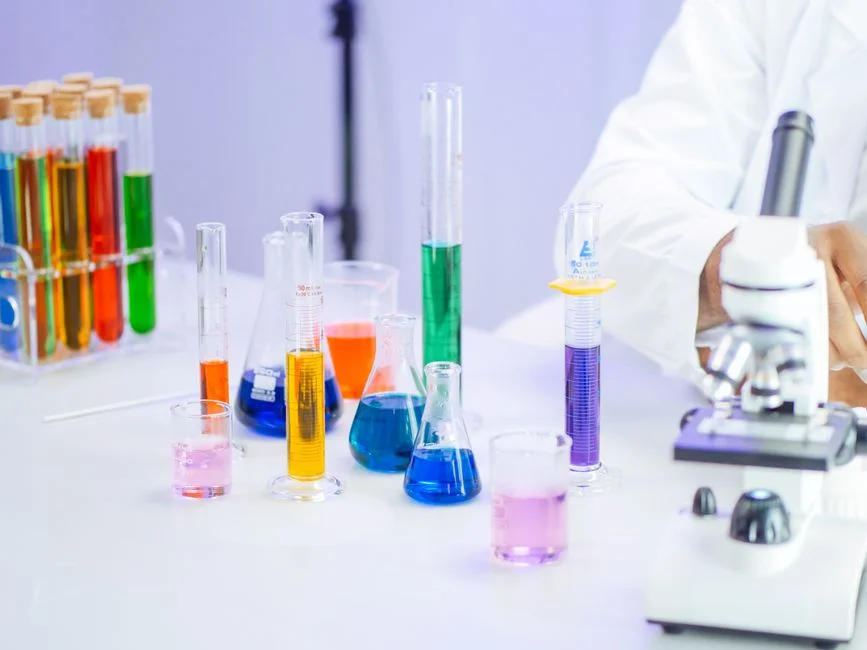
The standard DAF chemistry envelope for API mother liquor is 50–200 mg/L polyaluminium chloride (PAC) or ferric chloride as primary coagulant, paired with 1–5 mg/L anionic polyacrylamide flocculant, at pH 6.5–7.5. This is the Al/Fe hydrolysis sweet spot where coagulant species carry the highest cationic charge and neutralise the negative surface charge on emulsified oil droplets, allowing the polymer to bridge them into a buoyant floc (HydropureWater field data, 2026). The microbubble does not attach to free oil; it attaches to a flocculated oil droplet, so without the chemistry step the cell is just a bubble bath.
Coagulant choice is feed-driven. High-TDS or sulfide-laden mother liquor (sour refinery service water, desalter brine cross-bleeds) typically favours ferric chloride because Fe³⁺ is less affected by competing anions and produces a denser, easier-to-scrape float. Cleaner refinery streams — tank-farm runoff, hydrotest water — usually use PAC for lower sludge yield and a tighter floc that skims cleanly. Both coagulants hydrolyse effectively across pH 6.5–7.5, which is also the pH band where the anionic polymer reaches its open-chain conformation and bridging efficiency.
The single most common failure mode is over-dosing the polymer. Excess anionic polyacrylamide restabilises the emulsion (charge reversal on the droplet surface) and the DAF effluent oil climbs even though the dose is higher. This is a jar-test-gated parameter: 1, 2, 3, 5 mg/L polymer at the actual feed should be bench-tested before any procurement commitment. A PLC-controlled coagulant and polymer dosing skid with on-line streaming-current feedback is how the envelope is held in production, not by manual dosing.
| Chemical | Dose range | Function | Failure mode if overdosed |
|---|---|---|---|
| PAC (polyaluminium chloride) | 50–150 mg/L | Charge neutralisation, microfloc | High sludge, low pH drift |
| Ferric chloride (FeCl₃) | 75–200 mg/L | Charge neutralisation, denser floc | Acidification, Fe staining |
| Anionic polyacrylamide | 1–5 mg/L | Floc bridging, buoyant matrix | Emulsion restabilisation |
| pH adjustment (NaOH / H₂SO₄) | pH 6.5–7.5 | Optimal Al/Fe hydrolysis | Coagulant speciation collapses |
Micro-Bubble Sizing and Saturation Pressure
The flotation cell is only as good as the bubble. Microbubble size 10–80 µm, with the 30–50 µm band preferred for emulsified oil, is the design envelope: small enough to attach to fine floc and rise with the droplet, large enough to overcome hydrodynamic drag in the cell. Below 10 µm the bubble's terminal rise velocity is too low to lift floc in the available HRT; above 80 µm the bubble bursts at the surface without depositing the floc into the float blanket (HydropureWater field data, 2026). A saturation pressure of 4–6 bar(g) generates this size band in a packed saturator with 1–3 second residence.
The recycle ratio sits at 20–50% of the clarified effluent stream, and together with saturation pressure it sets the air-to-solids ratio (A/S) in the 0.005–0.060 (mass air : mass solids) range. Below A/S = 0.005 there is not enough bubble surface area to attach to the available floc; above A/S = 0.060 the cell is over-instrumented and the saturated water carries dissolved air that flashes turbulently, disturbing the float blanket. The recycle is pressurised rather than the full flow because pumping the entire mother liquor at 4–6 bar(g) would shear floc and re-emulsify oil that the API separator had already resolved.
Compressor versus pump choice is determined by flow stability. Positive-displacement pumps (typically progressing-cavity or rotary-lobe) are more common in refinery DAF skids because they hold saturation pressure independent of recycle flow swings, which happen on tank-farm service whenever a downstream filter is backwashing. Centrifugal blowers struggle to maintain the 4–6 bar(g) band when recycle flow drops by 30% during a backwash cycle, and the bubble size distribution shifts toward the coarse end of the envelope.
| Parameter | Design range | Effect on separation |
|---|---|---|
| Microbubble size | 10–80 µm (target 30–50 µm) | Attachment efficiency vs. rise velocity |
| Saturation pressure | 4–6 bar(g) | Sets dissolved air concentration |
| Recycle ratio | 20–50% of clarified effluent | Sets A/S ratio |
| Air-to-solids ratio (A/S) | 0.005–0.060 (mass : mass) | Floc-to-bubble matching |
| Saturator residence | 1–3 seconds at pressure | Equilibrium dissolution |
Hydraulic Design: HRT, Surface Loading, and Cell Geometry
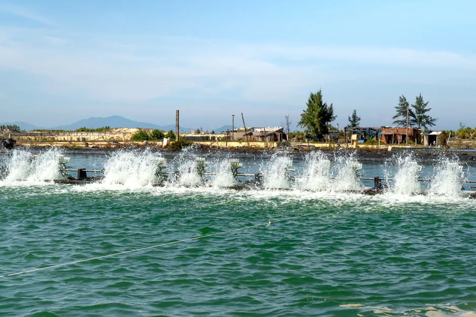
Hydraulic retention time of 15–30 minutes and a surface loading rate of 5–15 m/h define the DAF cell on API mother liquor (HydropureWater field data, 2026). HRT below 15 minutes is too short for the floc-bubble aggregate to reach the surface in the available cell depth; HRT above 30 minutes oversizes the vessel without lifting additional oil. Surface loading is the reciprocal of overflow rate — at 10 m/h on a 3 m wide cell, the unit can treat up to 30 m³/h per metre of weir length, which is the figure used to size the rectangular flotation tank.
Cell geometry is rectangular for standard refinery mother liquor service, with lamella or inclined plate packs only added when influent TSS exceeds ~500 mg/L. The plate packs stabilise the float blanket under high-solids loading; below 500 mg/L TSS the plates add hydraulic resistance and a fouling surface without lifting the removal rate. A spiral-blade float skimmer running at 0.5–1.0 m/min across the cell surface drives the floated sludge into a launder, while a bottom-sludge scraper at 0.3–0.5 m/min consolidates the settled solids. Combined underflow (float + bottom sludge) is typically 1–3% of throughput and routes to a sludge thickener or back to the slop oil system.
Standard refinery DAF cells cover 4–300 m³/h, and a DAF for API mother liquor lets the engineer match the design flow to a standard model rather than a custom build, with the saturator, recycle pump, skimmer, and scraper pre-integrated. Above 300 m³/h the cell is built in parallel trains rather than a single oversized vessel, which keeps HRT and surface loading inside the design envelope.
Reuse vs Discharge: Choosing the Effluent Target
The effluent number is the parameter that locks every upstream decision. For in-plant reuse — desalter make-up, wash water, cooling tower make-up — the target is <10 mg/L oil & grease, <30 mg/L TSS, and <100 mg/L COD, which the DAF typically hits directly without downstream polishing (HydropureWater field data, 2026). For compliant discharge to a municipal sewer or a sensitive receiving water, the target shifts to <20 mg/L oil & grease (the typical refinery consent number) and TSS <50 mg/L; the DAF is still the workhorse, but tighter regional limits (e.g., <5 mg/L oil & grease in some European jurisdictions) require MBR or RO polishing downstream. Jurisdiction-specific ceilings are mapped in the linked global industrial water reuse regulations 2026 reference, which an engineer should consult before the design freeze.
The CAPEX/OPEX framing is direct: a tighter reuse target that demands a downstream MBR or RO step adds 30–60% to the treatment train cost, but the DAF protects that downstream step by stripping the bulk oil first, which is what keeps membrane replacement intervals inside economic bounds. Designing to discharge when reuse is feasible leaves 70–90% of the treated water in the plant's water balance; designing to reuse when discharge is the constraint simply adds cost without benefit.
Putting It Together: A Practical Configuration Checklist
The configuration an engineer hands to procurement is a single integrated train, not a list of separate boxes. Influent envelope (50–500 mg/L oil, 100–800 mg/L TSS, 200–1,500 mg/L COD) → chemistry window (50–200 mg/L coagulant, 1–5 mg/L anionic polymer, pH 6.5–7.5) → hydraulic envelope (15–30 min HRT, 5–15 m/h surface loading, 20–50% recycle at 4–6 bar(g)) → expected effluent (<10 mg/L oil for reuse, <20 mg/L for discharge). The train is the DAF for API mother liquor paired with a PLC-controlled coagulant and polymer dosing skid and, for tight reuse or sensitive discharge, an MBR integrated wastewater treatment polishing step.
Procurement questions to confirm with the vendor: max throughput (m³/h) and peak instantaneous flow, peak influent oil and TSS measured at the API overflow, available footprint and headroom (saturator needs ~3 m vertical), recycle water source (clarified cell effluent, not raw feed), PLC integration with the upstream API separator and downstream biological or RO train, and the target effluent oil & grease the unit is being guaranteed against. With these answered, the configuration is specifiable and the train is buildable.
| Stage | Parameter | Design point |
|---|---|---|
| Influent envelope | Oil / TSS / COD / droplet size | 200 mg/L / 400 mg/L / 700 mg/L / 15–30 µm |
| Chemistry window | Coagulant / polymer / pH | 50–200 mg/L / 1–5 mg/L / 6.5–7.5 |
| Bubble envelope | Microbubble / pressure / A/S / recycle | 30–50 µm / 4–6 bar(g) / 0.005–0.060 / 20–50% |
| Hydraulic envelope | HRT / surface loading / cell depth | 15–30 min / 5–15 m/h / 2–3 m |
| Effluent target | Oil & grease / TSS (reuse) | <10 mg/L / <30 mg/L |
| Effluent target | Oil & grease / TSS (discharge) | <20 mg/L / <50 mg/L |
Frequently Asked Questions
What DAF configuration treats API mother liquor for reuse or discharge? 50–200 mg/L coagulant (PAC or FeCl₃), 1–5 mg/L anionic polymer, pH 6.5–7.5, microbubble size 30–50 µm, saturation pressure 4–6 bar(g), recycle ratio 20–50%, HRT 15–30 minutes, surface loading 5–15 m/h. Specified as a DAF for API mother liquor with an upstream PLC-controlled coagulant and polymer dosing skid.
What effluent oil & grease can a properly configured DAF deliver on API mother liquor? 80–95% oil & grease removal, with effluent oil typically <10 mg/L for reuse and <20 mg/L for standard refinery discharge consent (HydropureWater field data, 2026).
What is the air-to-solids ratio (A/S) for DAF on refinery mother liquor? 0.005–0.060 (mass air : mass solids), generated by a 4–6 bar(g) saturator on a 20–50% recycle sidestream of clarified cell effluent.
When is MBR or RO polishing required downstream of the DAF? When the effluent target is <5 mg/L oil & grease or <10 mg/L TSS — typically tighter regional reuse or sensitive receiving-water consents, as mapped in the global industrial water reuse regulations 2026 reference.