Why UPW Reject Is a Treatment Priority, Not a Waste Stream
UPW reject accounts for 40-60% of incoming city water at a typical 200 mm wafer fab, drawn from three sources: polishing-loop resin regeneration blowdown, RO reject from UPW makeup, and final-rinse overflow. Treating this stream as waste is a misreading of its value: Passmann and Joergensen measured UPW purification energy at 0.022 Wh/ml with a carbon intensity of 0.0104 gCO2-eq/g (cited in PMC8617369), so an 800 m³/day fab reject stream carries roughly 17,600 kWh/day of embedded energy. That figure alone reframes the DAF capital decision as a recovery investment, not a discharge cost.
Four contaminant families drive DAF design choices: colloidal silica (typically 5-30 mg/L) from polishing slurry carryover and quartz-tool wear; trace hydrocarbons from vacuum-pump exhaust and photoresist solvent residues; polishing-pad residues including ceria and alumina abrasives; and dissolved solids from resin regeneration cycles (Na⁺, Cl⁻, B). Colloidal silica is the most operationally stubborn because its zeta potential stays strongly negative above pH 6, resisting charge neutralization.
The reuse-versus-discharge fork splits the design envelope. Fabs targeting greater than 70% water reclaim route reject through DAF → UF → RO, with the DAF positioned to protect membrane flux. Fabs targeting only discharge compliance skip RO and pair DAF with chemical precipitation, breaking the cost curve by avoiding membrane replacement opex. The 2026 regulatory tilt toward mass-balance water-reuse permits is pushing more greenfield fabs into the pre-RO configuration, even when short-term economics favor discharge. For an engineering perspective on the broader process train, the SiC wastewater hybrid DAF-RO design outlines how this is unfolding in adjacent SiC wafer fabs.
DAF Configuration Fundamentals: Bubble Size, Recycle Ratio, and Contact Zone
Micro-bubble diameter is the single parameter that controls colloidal silica capture efficiency in UPW reject. Operating a saturator at 4-6 bar with a controlled orifice or needle-valve assembly produces 20-50 µm bubbles, which is the size range required to lift silica floc with a rise rate matching the 5-15 m/h surface loading rate of the separation zone. Smaller bubbles (20-30 µm) outperform larger ones for silica floc because the lower terminal velocity keeps the bubble attached to a lower-mass particle longer. For free oil removal, the same DAF tolerates larger bubbles because oil-bubble agglomerates are denser and more buoyant; this is why UPW reject DAFs are not simply oil-water DAFs with different chemistry.
Air-to-solids ratio (A/S) for UPW reject runs 0.02-0.05, lower than the 0.05-0.10 typical of oily wastewater because the colloidal load is dilute (typically 50-300 mg/L TSS in UPW reject versus 2,000-10,000 mg/L in refinery DAF feed). At A/S below 0.02, the float blanket is patchy and the effluent turbidity drifts up; above 0.05, the energy penalty for the saturator pump outweighs the marginal TSS gain. Recycle rate sits at 8-15% of influent flow, materially lower than the 20-30% used for high-FOG food-processing or refinery streams. The reason is stoichiometric: colloids need fewer attachment sites per unit mass than free oil droplets.
Hydraulic residence time (HRT) spans 15-25 minutes total across the flocculation, contact, and separation zones, even though the bubble-particle attachment reaction itself completes in under 5 minutes (per PMC8617369). Most of the HRT budget sits in flocculation (5-10 min) where polymer bridging builds micro-floc large enough to capture bubbles, and in the separation zone where the float blanket stabilizes. Surface loading rate on the separation zone is sized at 5-15 m/h; a typical dissolved air flotation (DAF) system spans 4-300 m³/h across 13 standard models, which covers the full range from 200 mm fab polishing-loop blowdown to TFT-LCD mother-glass rinse overflow.
| Parameter | UPW Reject DAF | Oil-Water DAF (reference) |
|---|---|---|
| Bubble diameter | 20-50 µm | 30-80 µm |
| Air:solids ratio (A/S) | 0.02-0.05 | 0.05-0.10 |
| Recycle rate | 8-15% | 20-30% |
| Total HRT | 15-25 min | 20-40 min |
| Surface loading rate | 5-15 m/h | 10-25 m/h |
| Saturator pressure | 4-6 bar | 4-6 bar |
Coagulant and Flocculant Pairing for UPW Reject
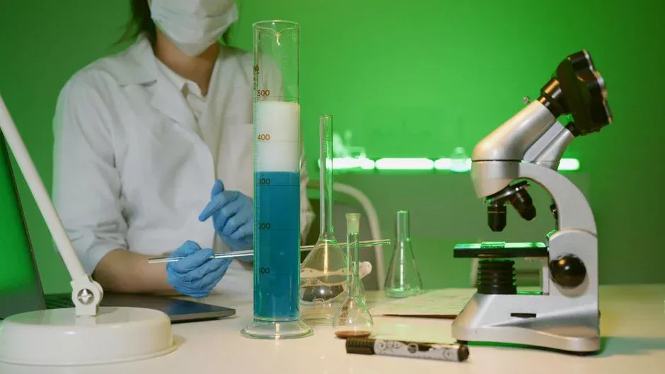
Ferric chloride at 30-80 mg/L is the default coagulant for silica-bearing UPW reject. The chemistry is pH-windowed: trivalent Fe³⁺ hydrolyzes to polynuclear species that destabilize colloidal SiO₂ between pH 7.0 and 8.5, where the silica zeta potential is most negative (typically -30 to -45 mV). Below pH 6.5, Fe³⁺ stays in monomeric form and underperforms; above pH 8.5, the coagulant precipitates as ferric hydroxide and overdoses without driving floc formation. Operate inside the 7.0-8.5 window and dose against the silica number, not the COD number.
Polyaluminum chloride (PAC) at 20-50 mg/L is the better pick when reject silica is low (under 5 mg/L) but polishing-pad residues and dissolved organics dominate. PAC's pre-hydrolyzed aluminum species work at pH 6.5-7.5 with roughly 30% less sludge generation than FeCl₃, which matters for fabs with limited sludge handling capacity. The trade-off is that PAC underperforms on colloidal silica because aluminum hydrolysis products carry lower positive charge density than ferric polynuclear species at neutral pH.
Cationic polymer at 0.5-2 mg/L — typically polyamine or polyDADMAC — is essential as a flocculation aid. Coagulant alone produces pinpoint floc that bubbles cannot lift; the polymer bridges micro-floc into 50-200 µm aggregates with the bubble attachment geometry needed for stable float. Anionic polymer is contraindicated for UPW reject because the colloid surface charge is cationic-to-neutral at polishing-loop pH (6.5-7.5), so anionic bridging finds no anchoring site. Dosing should run through a metering pump tied to a flow-paced signal on the equalization-tank transfer line, with an automatic chemical dosing skid handling the three-chemistry feed (coagulant, polymer, pH adjust) without operator intervention.
The jar-test protocol is straightforward and worth running for every new reject stream: 5 coagulant doses × 2 polymer types × 3 pH points = 30 vessels, screened first by turbidity removal (target 85%+ on a 1-L sample) and then by float solids volume. Skipping this step is the most common source of DAF underperformance at fabs; default dose numbers in vendor proposals assume a generic wastewater matrix that UPW reject is not.
| Coagulant | Dose | Operating pH | Best For | Sludge Index |
|---|---|---|---|---|
| FeCl₃ | 30-80 mg/L | 7.0-8.5 | Colloidal silica (5-30 mg/L SiO₂) | High |
| PAC | 20-50 mg/L | 6.5-7.5 | Polishing-pad residues, low-silica organics | Medium |
| Cationic polymer (polyamine/polyDADMAC) | 0.5-2 mg/L | 6.5-8.0 | Always paired; bridges micro-floc to bubbles | Low |
| Anionic polymer | Not recommended | — | Contraindicated for UPW reject colloid charge | — |
Pre-RO vs. Post-RO DAF Placement: The Reuse Decision
DAF placement in the process train is the single highest-impact design decision for UPW reject systems, because it determines whether the downstream RO membranes can run sustainably. Pre-RO DAF sits between the reject equalization tank and the UF/RO polish train, removing colloidal silica, hydrocarbons, and suspended solids before they reach the membrane. Research on pretreated industrial wastewater shows that an industrial RO system can be operated up to 40% recovery without flux decline when aliphatic hydrocarbon stays below 2 mg/L in the DAF effluent (MDPI Membranes 15/3/94). That is a quantitative anchor for sizing flocculation: under-dose polymer, and the 2 mg/L ceiling gets crossed within a few weeks of operation.
Post-RO DAF treats RO concentrate to reduce volume before either discharge or a thermal ZLD stage. The hydraulic load is roughly 60% lower than pre-RO because RO recovery has already pulled 40-60% of the water through as permeate. But the chemistry is harder: TDS runs 1,000-3,000 mg/L versus 50-200 mg/L upstream, and the higher ionic strength compresses the double layer around the colloid, which means coagulant demand rises by 20-30% for the same TSS removal efficiency. Recycle rate goes up to 12-15% and HRT stretches to 25-30 minutes to compensate.
For discharge-only plants, DAF alone (no RO) is paired with chemical precipitation for heavy metals and breaks the cost curve versus building a full reuse train. The pre-RO configuration is the 2026 best practice for fabs pursuing greater than 85% water reclaim, with a smaller pre-RO DAF polishing the polishing-loop blowdown and a larger post-RO DAF handling the concentrate stream. The CMP slurry RO pretreatment guide walks through the upstream feed-side decisions in more detail for fabs where CMP blowdown dominates the reject stream.
| Parameter | Pre-RO DAF (reuse) | Post-RO DAF (concentrate/discharge) |
|---|---|---|
| Influent TDS | 50-200 mg/L | 1,000-3,000 mg/L |
| Influent TSS | 50-300 mg/L | 100-500 mg/L |
| Coagulant demand (FeCl₃) | 30-80 mg/L | 50-100 mg/L |
| Recycle rate | 8-12% | 12-15% |
| Total HRT | 20-25 min | 25-30 min |
| Aliphatic HC target (to RO) | < 2 mg/L | N/A (after RO) |
| Sludge yield | 0.3-0.6% of flow | 0.5-0.8% of flow |
Sizing the DAF for a Typical Fab: A Worked Example
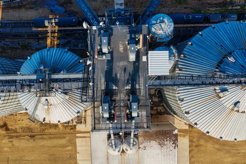
Take a 200 mm wafer fab producing 800 m³/day of UPW reject and targeting 60% reclaim. That splits into 320 m³/day routed pre-RO toward reuse and 480 m³/day routed through a separate discharge DAF (or sent directly to chemical precipitation for metals). Sizing the pre-RO DAF at a 20-minute HRT gives: 320 m³/day ÷ 24 hr/day ÷ 60 min/hr × 20 min ≈ 4.4 m³ of active volume. The discharge DAF at 20-minute HRT needs 480 ÷ 24 ÷ 60 × 20 ≈ 6.7 m³. Both sit comfortably inside the DAF catalog envelope of 4-300 m³/h capacity across the standard model line.
Sludge yield from both DAFs combined runs 0.3-0.6% of reject volume, or 2.4-4.8 m³/day of floated solids at roughly 2-4% dry solids. Route that to a plate-and-frame filter press for dewatering to under 65% moisture; the resulting cake is typically non-hazardous in most jurisdictions and can be landfilled or, where regulations allow, sent to a cement kiln. Power draw breaks down as 0.5-1.2 kWh/m³ treated for the recirculation pump (the saturator feed) and 0.05-0.1 kWh/m³ for the compressed-air system, so the combined DAF power budget is around 480-720 kWh/day across both units.
Sanity-checking the CAPEX case against the embedded energy figure: 800 m³/day × 1,000 L/m³ × 0.022 Wh/ml = 17,600 kWh/day of energy is locked in the reject. At an industrial electricity tariff in the 0.08-0.12 USD/kWh range, that is 1,400-2,100 USD/day of energy value on the table. Reuse CAPEX of a DAF-UF-RO train for an 800 m³/day fab typically lands in the 1.5-3.0 M USD range, which pays back inside 2-4 years on the energy value alone, before counting avoided water-purchase costs and discharge fees. The arithmetic is decisive for any fab where city-water tariffs exceed 2 USD/m³. For a comparable process train on the TFT-LCD side, the TFT-LCD hybrid A/O-MBR-RO design gives a parallel CAPEX breakdown for mother-glass fabs with similar reclaim economics.
Compliance Anchors and 2026 Discharge Limits for UPW Reject
For fabs in China discharging to municipal sewer, GB 39731-2020 sets COD ≤ 500 mg/L, suspended solids ≤ 400 mg/L, and total silicon ≤ 30 mg/L for semiconductor effluent. A properly operated DAF typically delivers SS under 30 mg/L comfortably, so the SS ceiling is not the binding constraint. Total silicon is the constraint that drives coagulant choice: FeCl₃ at 40-60 mg/L with pH 7.5-8.0 reliably pulls colloidal silica below 20 mg/L on UPW reject; PAC at the same dose will leave the stream closer to 25-30 mg/L.
For fabs in the European Union, the Industrial Emissions Directive 2010/75/EU BAT-AEL for surface treatment of metals and plastics applies if reject co-mingles with finishing wastewater. DAF alone may not meet TOC limits without a polishing step (activated carbon or advanced oxidation) because dissolved polishing-loop organics below 1 kDa pass through the float blanket. For fabs pursuing reuse, SEMI F63-0214 sets resistivity ≥ 0.5 MΩ·cm and TOC ≤ 200 ppb for non-critical rinse reuse — DAF only gets the water to UF/RO feed spec, not to the reuse spec. The reuse-quality number is hit after RO and a final mixed-bed polisher, not in the DAF stage.
The 2026 regulatory trend is the shift from end-of-pipe discharge concentration limits to mass-balance-based water-reuse permits. Several jurisdictions are now requiring new fabs to demonstrate a specified percentage of incoming city water returned to the process, regardless of the discharge concentration. This regulatory shift makes pre-RO DAF the default configuration for greenfield projects, because it is the only placement that supports the mass-balance accounting. The corresponding compliance monitoring requirements are detailed in the EU IED monitoring for surface treatment compliance guide.
Frequently Asked Questions
What coagulant dose treats UPW reject in DAF?
FeCl₃ at 30-80 mg/L paired with 0.5-2 mg/L cationic polymer is the default for silica-bearing UPW reject, operating at pH 7.0-8.5. PAC at 20-50 mg/L substitutes when reject silica is below 5 mg/L and polishing-pad residues dominate, with about 30% less sludge generation but weaker silica removal (HydropureWater field data, 2026).
Should DAF be placed before or after RO for UPW reject reuse?
Pre-RO DAF is the 2026 default for any fab targeting reuse: it removes colloidal silica and hydrocarbons before the membrane, enabling sustainable operation at 40%+ recovery with aliphatic hydrocarbon held below 2 mg/L (per MDPI Membranes 15/3/94, 2026). Post-RO DAF treats concentrate before discharge or ZLD and requires 20-30% higher coagulant demand.
What is the typical hydraulic residence time for a UPW reject DAF?
Total HRT across flocculation, contact, and separation zones is 15-25 minutes. The bubble-particle attachment reaction itself completes in under 5 minutes, so most of the HRT budget sits in flocculation and float-blanket stabilization (per PMC8617369, 2026).
How is DAF configured differently for reuse versus discharge at a fab?
Reuse trains pre-RO DAF at 8-12% recycle with 20-25 min HRT and target < 2 mg/L aliphatic hydrocarbon to protect RO flux. Discharge-only trains route reject through DAF plus chemical precipitation, skip RO, and break the CAPEX curve; this suits fabs with low city-water tariffs or low discharge fees (HydropureWater field data, 2026).
Related Equipment
- industrial RO system — specifications, capacity range, and technical data