Why Formation Rinse Water Breaks a Standard MBBR
Formation rinse water carries a contaminant load that strips biofilm from MBBR carriers within hours of contact. During lithium-ion cell formation, the SEI layer is built on the anode through controlled electrochemical cycling in LiPF₆-based electrolyte (typically LiPF₆ in EC/EMC/DMC with VC and FEC additives). Each formation and aging cycle ends with a deionized-water rinse that washes off electrolyte carryover, and that rinse becomes the wastewater stream an ETP must treat (per ScienceDirect 2024 on biofilm colonization). The resulting profile is hostile: pH 2–4 from HF and H₃PO₄ hydrolysis, COD 200–800 mg/L from carbonate solvent breakdown, fluoride 50–500 mg/L from LiPF₆ hydrolysis, lithium 5–50 mg/L, trace Ni/Co/Mn up to 30 mg/L from cathode contact, and emulsified oil/grease 20–200 mg/L from cell-handling equipment.
MBBR performance depends on stable bacterial colonization on carriers, with aeration-driven movement of the media providing continuous mass transfer (ScienceDirect 2024). Frontiers in Environmental Science (2026) confirms that MBBR's advantages — high biomass on carriers and stable pollutant removal efficiency — only hold when suspended solids and oils are removed upstream of the biological step. In a formation-rinse stream, pH below 4 lyses nitrifying bacteria, fluoride above 20 mg/L inhibits enzymatic activity, and free oil coats carrier surfaces and prevents biofilm attachment. The combination kills the biological step within one HRT, requiring a dedicated pretreatment train between the formation floor drains and the MBBR basin.
The Five Pretreatment Stages Required Before MBBR
Effective pretreatment requires a specific sequence to condition the water for each subsequent stage and prevent downstream biomass compromise.
- Equalization and pH pre-adjustment. A buffered EQ tank with HRT 8–24 h dampens flow and pH swings from batch formation cycles. Mechanical agitation at low shear (G ≈ 50–100 s⁻¹) keeps solids in suspension without emulsifying oils further. Caustic dosing in-line lifts pH to 5.5–6.5 to protect downstream fluoride-reactor metallurgy.
- Fluoride removal by calcium precipitation. CaCl₂ dosed at 200–400% of stoichiometric F⁻ drives precipitation of CaF₂ (Ksp ≈ 3.9 × 10⁻¹¹). A single stage typically leaves 20–40 mg/L F⁻ residual, so a two-stage configuration is required: stage 1 at pH 9–10 with CaCl₂, stage 2 with NaOH pH polish and a clarifier. A polishing adsorption stage with activated alumina or calcium phosphate can drop residual F⁻ below 10 mg/L when needed.
- Oil, FOG, and colloidal solids removal. Dissolved air flotation is the proven primary separation for high-FOG industrial wastewater. A DAF system for oil and FOG removal upstream of MBBR collapses emulsified oil and floats colloidal solids in a single step, typically targeting outlet oil/grease ≤ 20 mg/L and SS ≤ 80 mg/L. DAF must follow fluoride precipitation so that metal-hydroxide floc does not overload the float layer.
- Heavy-metal coagulation. FeCl₃ at 50–150 mg/L or polyaluminum chloride (PAC) at 30–100 mg/L, dosed at pH 8–9, drives hydroxide co-precipitation of residual Ni, Co, Mn, and Li into the fluoride sludge matrix. This stage doubles as a phosphorus-removal step if any phosphate carryover is present, and the sludge reports to the same dewatering line as the CaF₂ cake.
- pH re-adjustment and final filtration. The MBBR feed is brought to pH 6.5–8.5 with HCl or CO₂ stripping, polished through a multimedia or bag filter to SS ≤ 50 mg/L, and sampled against the feed spec before entering the MBBR basin. PLC-controlled chemical dosing for fluoride and pH adjustment keeps each setpoint within ±0.2 pH and ±5 mg/L F⁻, which is the tolerance band MBBR biomass actually needs.
Frontiers (2026) explicitly notes that suspended solids and oils must be removed upstream of any biological reactor, including MBBR. The five stages above are the formation-rinse-specific implementation of that requirement, with the heavy-metal and fluoride windows inserted because no top-ranking MBBR pretreatment guide addresses this stream.
| Stage | Unit Operation | Primary Target | Outlet to Next Stage |
|---|---|---|---|
| 1 | Equalization + pH pre-adjust | Flow/pH dampening | pH 5.5–6.5, HRT 8–24 h |
| 2 | Two-stage CaCl₂ precipitation | Fluoride | F⁻ ≤ 20 mg/L (≤ 10 mg/L with polish) |
| 3 | DAF flotation | Oil/FOG, colloidal SS | Oil ≤ 20 mg/L, SS ≤ 80 mg/L |
| 4 | FeCl₃/PAC coagulation | Ni/Co/Mn/Li | Total heavy metals ≤ 5 mg/L |
| 5 | pH adjust + multimedia filter | MBBR feed spec | pH 6.5–8.5, SS ≤ 50 mg/L, F⁻ ≤ 20 mg/L, oil ≤ 10 mg/L |
Design Parameters Each Stage Must Hit
Standardized operating windows ensure the ETP can handle varying influent loads across different formation SKUs.
| Parameter | EQ Tank | Fluoride Reactor | DAF | Coagulation | MBBR Feed Spec |
|---|---|---|---|---|---|
| HRT / contact time | 8–24 h | 30–60 min (×2 stages) | 20–40 min | 15–30 min | — |
| pH | 5.5–6.5 (out) | 9–10 (in) | 7–8.5 | 8–9 | 6.5–8.5 |
| Chemical dose | NaOH to pH 5.5–6.5 | CaCl₂ 200–400% stoichiometric vs F⁻ | PAM 1–3 mg/L | FeCl₃ 50–150 mg/L or PAC 30–100 mg/L | — |
| Target outlet | Steady flow, pH controlled | F⁻ ≤ 20 mg/L | Oil ≤ 20 mg/L, SS ≤ 80 mg/L | Ni/Co/Mn/Li ≤ 5 mg/L total | F⁻ ≤ 20 mg/L, oil ≤ 10 mg/L, SS ≤ 50 mg/L |
| Temperature | Ambient (20–35°C) | 20–35°C | 20–35°C | 20–35°C | 15–35°C |
| Instrumentation | pH probe, level, temperature | pH, F⁻ ion-selective electrode, ORP | TSS, surface scum sensor | pH, streaming current | pH, F⁻ ISE, TSS, oil-in-water analyzer, Cl⁻ monitor |
Two operating notes protect the MBBR. First, residual free chlorine above 0.5 mg/L strips nitrifying biofilm, making a Cl⁻ monitor on the feed non-negotiable. Second, MBBR's documented advantage — high biomass on carriers and stable pollutant removal efficiency (Frontiers 2026) — is the reason this pretreatment train exists; every parameter window above is sized to keep the carrier surface available for colonization rather than for chemical or particulate fouling.
Equipment Selection by Stage
Hardware selection must prioritize corrosion resistance and mixing efficiency to maintain the required chemical setpoints.
EQ tank: HDPE-lined or FRP-coated concrete, sized for 8–24 h at peak formation rinse flow. Mechanical agitator at low G (50–100 s⁻¹) keeps solids suspended without shearing emulsified oil into smaller droplets that DAF cannot recover. pH and temperature probes feed the PLC for caustic trim.
Fluoride reactor: PE or FRP tank with slow-speed axial-flow mixer, G value 200–500 s⁻¹ — high enough to distribute CaCl₂ uniformly but low enough to keep CaF₂ floc intact. Two reactors in series with an inline clarifier or lamella between them handle the 20–40 mg/L residual that a single stage cannot reach.
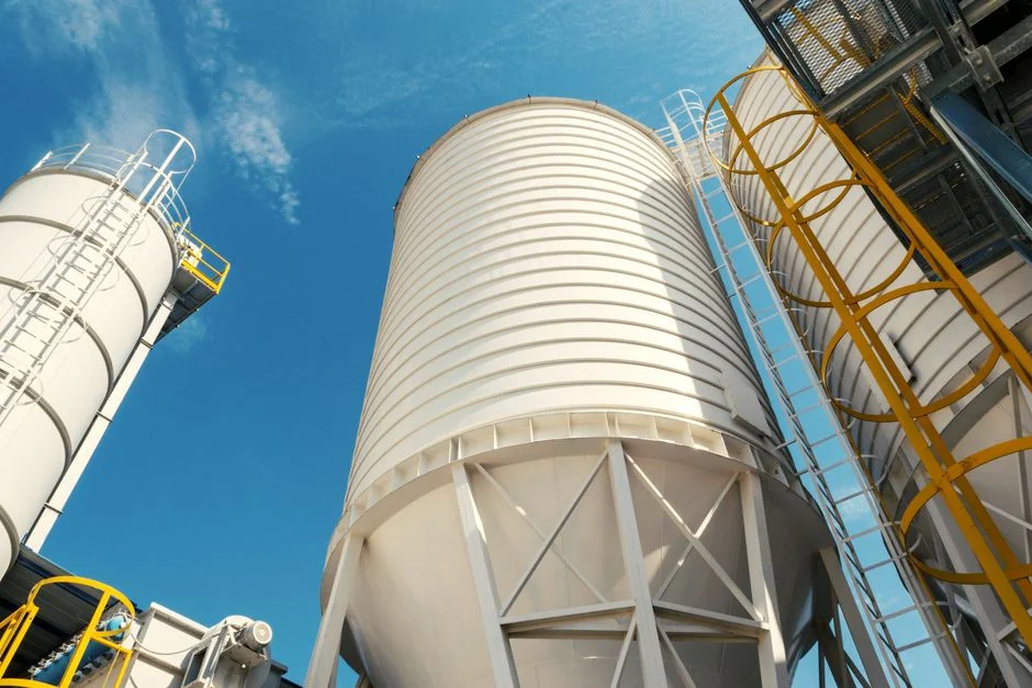
DAF: Micro-bubble contact zone with recycle ratio 20–40%, automatic skimmer, and an integrated polymer makeup unit. DAF units are specified across industrial pretreatment duties from 4–300 m³/h, covering the rinse flow from a single formation line through a full gigafactory ETP header. The DAF sits after the fluoride reactor so metal-bearing floc reports with the float layer rather than blinding downstream filtration.
Chemical dosing: PLC-controlled injection of CaCl₂, NaOH, FeCl₃, and PAM, sized from the influent F⁻ and metal loads. An automatic chemical dosing system with redundant pumps and online analyzers in trim mode keeps each setpoint inside the parameter table without operator intervention.
Sludge handling: CaF₂ plus metal hydroxide sludge from the fluoride reactor, DAF float, and clarifier underflow is sent to a plate-and-frame filter press for CaF₂ and metal hydroxide sludge. Filter press operation typically reaches 25–35% DS cake, providing the disposal-side endpoint for this stream and a design basis when sizing the dewatering line alongside the MBBR feed train.
Frequently Asked Questions
What pH must battery formation rinse hit before an MBBR? The feed must land between pH 6.5 and 8.5. Below 6.0, nitrifying bacteria on MBBR carriers lose activity within hours; above 8.5, free ammonia shifts the nitrification equilibrium unfavorably. A two-stage trim — NaOH up to 9–10 in the fluoride reactor, HCl or CO₂ back to neutral — keeps MBBR biomass inside its operating window (HydropureWater field data, 2026).
What fluoride limit protects MBBR biomass? F⁻ must be ≤ 20 mg/L at the MBBR inlet, and ≤ 10 mg/L is the safer design target for nitrification-heavy carriers. Two-stage CaCl₂ precipitation at pH 9–10 reaches the 20 mg/L level; a downstream activated-alumina polish is needed if the raw rinse carries more than 300 mg/L F⁻ or if the MBBR is sized for ammonia removal rather than just COD polishing.
Is a DAF mandatory before MBBR for formation rinse? Yes, for any stream with more than 20 mg/L emulsified oil or 80 mg/L colloidal SS. Free oil coats carrier surfaces and blocks biofilm attachment; SS abrades biofilm as carriers collide. Frontiers (2026) treats suspended-solids and oil removal as a precondition for MBBR performance, not an option, and formation-rinse streams sit at the high end of the FOG range for industrial wastewater.
What heavy-metal concentrations stop the MBBR from working? Total Ni/Co/Mn/Li above 5 mg/L at the feed begins to inhibit nitrification, and above 20 mg/L the MBBR effectively shuts down. FeCl₃ or PAC coagulation at pH 8–9 removes these metals by hydroxide co-precipitation into the same sludge matrix as the CaF₂, which simplifies dewatering to a single 2026 ETP process train for a battery gigafactory line.
Why two fluoride precipitation stages instead of one? CaF₂ solubility alone limits a single stage to roughly 20–40 mg/L F⁻ residual, which is above the MBBR tolerance. A second stage at pH 9–10 with fresh CaCl₂ and a settling or lamella step pushes