Separate Wastewater Streams Before Choosing Equipment
A data center in UEskuedar should source-separate cooling or evaporative-cooler blowdown, sanitary sewage, equipment washwater, process wastewater, stormwater and construction-derived wastewater before selecting treatment. The route depends on whether each stream will be discharged, sewered, reused for cooling makeup, reused for non-cooling purposes or handled through an approved bypass. For cooling blowdown, characterize pH, conductivity, TDS, suspended solids, turbidity, temperature, hardness, alkalinity, residual chemicals and cycles of concentration. At 4 CoC, theoretical blowdown is 25% of makeup water; at 6 CoC, it is 20%. UF can provide a low-turbidity, low-solids barrier, while RO requires dissolved-salts removal, pretreatment and concentrate management. Final Turkish requirements must be confirmed in writing before equipment sizing.
Separate the streams before defining a common treatment train. A cooling blowdown stream, sanitary stream and washwater stream have different hydraulic profiles, contaminant controls and receiving routes. Combining them can increase equalization and treatment capacity while obscuring which barrier is actually required. The data-center wastewater and cooling-blowdown treatment guide provides a comparable source-segregation framework.
| Stream | Design information to obtain | Likely treatment decision | Unresolved approval or input |
|---|---|---|---|
| Cooling or evaporative-cooler blowdown | Normal and peak flow; evaporation; CoC; chemical program; temperature and chemistry | Targeted filtration, chemical control or membrane barrier based on the selected discharge or reuse route | Written Turkish discharge, sewer or reuse conditions; cooling-vendor limits |
| Sanitary wastewater | Flow, organic loading, seasonal variation and collection arrangement | Biological treatment or site-specific pretreatment; keep separate from cooling polishing | Applicable sanitary design requirements and receiving utility conditions |
| Equipment washwater | Detergents, oil and grease, suspended solids and episodic discharge pattern | Filtration, equalization and chemical control where identified by analysis | Approved discharge route and treatment objectives |
| Process wastewater | Process origin, chemicals, metals, flow variation and emergency drains | Source-specific pretreatment before any selected final route | Written acceptance conditions for the receiving route |
| Stormwater | Drainage area, rainfall response, contaminated hardstanding and bypass route | Segregation, collection and treatment only where the site assessment requires it | Authority-approved stormwater route |
| Construction-derived wastewater | Commissioning flushes, cleaning chemicals, sediment and temporary discharge plan | Separate temporary treatment and disposal plan | Construction-period discharge authorization |
For every stream, record normal flow, variability, emergency or bypass route, final destination and responsible authority. These fields are more useful than facility megawattage because they define the actual treatment duty. Hydraulic and operating data supplied by the cooling and facility contractors should be reconciled with site measurement before award.
Set the Destination and Required Water-Quality Barrier
The final use determines the required treatment barrier, so the written route condition must precede equipment selection. Obtain environmental-discharge, sewer-connection, water-abstraction and reuse conditions from the responsible Turkish authorities and receiving utility. Do not treat a generic discharge limit, a permit from another jurisdiction or a cooling-vendor target as a confirmed Turkish requirement.
For discharge, confirm the applicable pH, temperature, solids, dissolved-salts and residual-chemical conditions before fixing performance targets. For cooling-makeup reuse, assess conductivity, hardness, scaling, corrosion and biological-control risks against the range of cycles of concentration that the cooling vendor can safely support. For toilet flushing, equipment washing or another non-cooling use, obtain the receiving equipment’s water-quality and public-health requirements.
Closed-loop and direct-to-chip systems do not remove the need for wastewater planning. They can create smaller maintenance streams containing glycol, corrosion inhibitors, suspended solids or dissolved metals, according to Valicor’s “How Data Centers Stay Cool: Cooling Towers, Liquid Cooling, Space & More.” Their initial fill, flushing, draining and maintenance flows must therefore remain in the stream inventory. The comparison of discharge and cooling-reuse routes for data-center blowdown illustrates why destination selection comes first.
| Selected destination | Water-quality basis | Treatment implication | Evidence required before award |
|---|---|---|---|
| Direct or indirect discharge | Written conditions for pH, temperature, solids, dissolved salts and residual chemicals | Filtration plus targeted chemical control; disinfection only where required | Authority correspondence, permit or equivalent written route conditions |
| Sewer connection | Receiving utility’s connection and acceptance conditions | Site-specific pretreatment; no assumption that cooling polish is sufficient | Utility approval and required sampling basis |
| Cooling-makeup reuse | Conductivity, hardness, scaling, corrosion and biological-control limits | Filtration, chemical control and advanced treatment where justified | Cooling-vendor limits, safe CoC range and written reuse permission |
| Toilet flushing or washing | Destination-specific quality and public-health requirements | Filtration and disinfection as required by the reuse route | Confirmed reuse application and receiving-equipment requirements |
| Emergency or bypass route | Capacity, holding time and approved destination | Equalization, diversion controls and a non-treatment contingency | Approved bypass route and operating responsibility |
Keep confirmed conditions separate from design assumptions until the responsible authority approves the basis. A reuse volume is not equivalent to permanent water consumption: water returned to a cooling loop has an operating and water-balance effect, while permanently consumed water changes the site’s consumption baseline.
Characterize Cooling Blowdown and Build the Water Balance
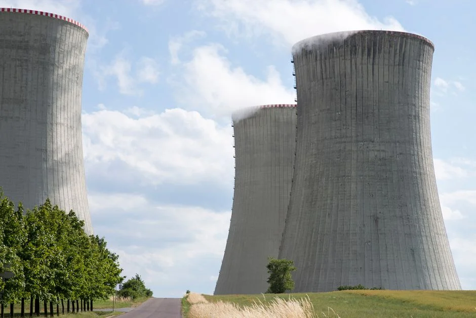
Measured blowdown and a reconciled water balance are the defensible basis for treatment capacity. The cooling-vendor water balance provides the starting model, but it does not replace field reconciliation. Analyze pH, conductivity, TDS, suspended solids, turbidity, temperature, hardness, alkalinity and residual treatment chemicals, and obtain the vendor’s water-balance method, chemical program, expected CoC range, seasonal conditions and upset-control philosophy.
At 4 CoC, theoretical blowdown is 25% of makeup-water volume; at 6 CoC, it is 20%. Genesis Water Technologies, as reported in HydropureWater’s 2026 assessment, also states that actual blowdown can exceed theoretical calculations by 15–30% because of unmeasured losses and emergency dumps. The theoretical equation is therefore a screening calculation, not final plant sizing.
Reconcile makeup, evaporation, blowdown, discharge, reuse and emergency dumping. Continuous flow and concentration measurements are needed to validate actual consumption and CoC. Record normal flow and separate emergency-dump events, then determine the equalization and treatment duty. Peaks and upsets should be evaluated as specific operating cases rather than used to size every stream against an unverified extreme condition.
| Water-balance item | Required record | Use in the treatment decision |
|---|---|---|
| Makeup water | Continuous flow and operating period | Establishes the upstream water demand and theoretical blowdown basis |
| Evaporation | Cooling-vendor calculation reconciled with site operation | Distinguishes evaporation loss from intentional blowdown |
| Normal blowdown | Measured flow and validated cycles of concentration | Sets the normal treatment-train capacity |
| Discharge | Final destination flow and quality | Tests compliance with the written route conditions |
| Reuse | Verified flow and return-to-loop demand | Determines the reusable production requirement and storage need |
| Emergency dumping | Event flow, duration, chemistry and approved route | Defines equalization, diversion and upset-management requirements |
Size the normal train from measured or cooling-vendor-supported blowdown, then evaluate peaks and upsets separately. Link storage to the intended reuse, including seasonal variation, laboratory or truck turnaround time and the consequences of a reuse-system outage. The data-center blowdown treatment methodology and the data-center cooling-blowdown reuse design provide related approaches to water-balance development.
Match the Treatment Train to the Governing Contaminants
Select each barrier against the governing contaminant and final use, not against a generic list of technologies. Filtration or dissolved air flotation is relevant where suspended solids, colloids, oil and grease or floating material are the principal constraints. DAF should not be added automatically to relatively clean cooling blowdown without an identified contaminant or floatable load.
UF is appropriate where a low-turbidity, low-suspended-solids barrier is required before sensitive equipment or downstream membranes. HydropureWater’s UF systems use 0.03-micron PVDF membranes, accept turbidity up to 300 ppm, and include automatic backwash and air scour, according to the 2026 HydropureWater assessment. For the proposed package, review the UF system for cooling-blowdown pretreatment against the measured feed chemistry and required filtrate quality.
RO is justified where dissolved-salts removal or high-purity reuse is required. The comparison for an industrial RO system for dissolved-salts removal must include feed characterization, pretreatment, energy, membrane replacement and concentrate management. MBR belongs where biological treatment and membrane solids separation are required; it does not replace targeted cooling-blowdown polishing.
Open Engineering Inc’s 2026 life-cycle assessment found that the UF+RO wastewater scenario used more than five times the freshwater case’s energy, while improved CoC reduced blowdown and chemical consumption. That result supports explicit comparison of treatment energy and residual management against the discharge or reuse benefit; it does not establish a UEskuedar energy value.
| Governing condition | Potential barrier | Required checks | Residual or operating issue |
|---|---|---|---|
| Suspended solids, colloids, oil and grease or floating material | Filtration or DAF | Feed characterization, removal efficiency and equalization demand | Residual-solids or sludge destination |
| Low turbidity and low suspended solids required | UF | Feed chemistry, filtrate quality, backwash sequence and integrity verification | Backwash waste and membrane replacement |
| Dissolved salts or high-purity reuse | RO with justified pretreatment | Feed chemistry, recovery basis, energy, membrane replacement and monitoring | Concentrate management |
| Biological treatment and membrane solids separation | MBR | Organic loading, aeration, solids separation and final-quality barrier | Sludge handling |
| Microbiological or chemical risk in reuse | Disinfection and chemical control | Contact performance, residual monitoring and receiving-use requirements | Residual limits and chemical handling |
Verify Capacity, Controls and Acceptance Before Award
A compliant purchase order should define the complete operating package, not only the treatment skid. Each proposal must identify the source stream, measured flow basis, water chemistry, final use, bypass route, utilities, controls, residual-waste destination, commissioning tests, operator training and local support. Equipment names alone do not establish that the stream will be treated to the required route condition.
Compare total cost of ownership, including energy, chemicals, filter media or membrane replacement, sludge or concentrate handling, monitoring, maintenance and downtime. The same comparison must separate returned reuse water from permanent consumption because those outcomes have different operating and water-balance effects.
For UF and RO trains, define tests around membrane integrity or filtrate quality, solids removal, automatic controls, alarms, power loss and chemical-out-of-service conditions. Every test needs a sampling point, operating condition, acceptance basis and required record. The RO and UF membrane and filter-element documentation should be linked to those acceptance requirements rather than used as an equipment-only specification.
- Confirm that the proposed duty uses measured or cooling-vendor-supported flow and a documented operating envelope.
- Check materials, instrument ranges, redundancy, utilities, bypass controls and residual handling against the design basis.
- Require signed flow, quality, controls, alarms and power-loss test records, calibrated instruments and punch-list closeout.
- Verify the measured water balance, reuse result, applicable Turkish conditions and monitoring records before acceptance.
- Obtain operator training, operating manuals, remote-monitoring arrangements, spares, warranty terms and replacement-parts pricing.
A defensible UEskuedar price cannot be stated without measured flow, the selected treatment objective, site water chemistry and local utility tariffs. Request itemized capital cost and operating costs rather than comparing a membrane price with a complete plant price. Treat unresolved reuse permission, discharge conditions and site data as approval gaps, not as equipment-selection variables that can be assumed away.
Frequently Asked Questions
How should a UEskuedar cooling-blowdown train be sized?
Size it from reconciled measured blowdown and verified reuse demand, not facility megawattage alone. Use the cooling vendor’s water balance as the starting model, reconcile it with field flow and concentration measurements, and assess peaks, maintenance drains and emergency dumps as defined operating cases. Genesis Water Technologies, reported in HydropureWater’s 2026 assessment, states that actual blowdown can exceed theoretical calculations by 15–30%, so theoretical CoC calculations alone are insufficient for final sizing.
What should be included when comparing treatment suppliers?
Compare suppliers against the complete scope. Require the proposed flow and water chemistry, end use, bypass route, utilities, automatic controls, residual-waste destination, commissioning tests, operator training, local support and relevant references. Obtain itemized capital and operating costs, including energy, chemicals, media or membrane replacement, sludge or concentrate handling, monitoring, maintenance and downtime, together with warranty and replacement-parts pricing. A lower skid price is not comparable if utilities, controls or residuals remain undefined.
Can final equipment be selected before Turkish discharge and reuse conditions are confirmed?
No. Obtain written requirements from the responsible Turkish authorities and receiving utility for environmental discharge, sewer connection, water abstraction and reuse, and keep confirmed conditions separate from design assumptions. For cooling-makeup reuse, also obtain the cooling vendor’s safe CoC range and water-quality limits. If those inputs remain unavailable, the project can develop a treatment concept but cannot defensibly fix the final performance specification.
Should reuse water be included in the facility’s permanent water-consumption baseline?
No. Distinguish reuse returned to the cooling or process system from water permanently consumed. Record both because they represent different project outcomes: one changes the operating water balance while the other changes consumption. The treatment sizing and operating baseline should separately identify measured blowdown, discharge, reuse and permanent consumption.
Related Equipment
- industrial RO system for dissolved-salts removal — specifications, capacity range, and technical data