
Map the Wastewater Before Selecting Equipment
Waste-incineration plant wastewater treatment should be selected from the waste inventory, combustion method and contaminants—not from a generic incinerator label. Hazardous-waste incinerator effluent may contain halogens, heavy metals and other pollutants requiring source control, equalization, pH adjustment, precipitation, biological treatment or membrane polishing as analysis confirms. EPA describes sewage-sludge incineration systems as multiple-hearth, fluidized-bed and electric types; cyclone reactors and rotary kilns are also used, although wet oxidation is not strictly incineration. The practical output is a contaminant-to-equipment matrix and a pre-specification sampling plan covering flow, pH, COD, BOD, TSS, oil and grease, halogens and metals.
The academic treatment framework in Remediation Journal, “Treatment of hazardous waste incineration wastewater,” defines rotary-kiln effluent as a unit-operations problem involving wastes containing halogens and heavy metals. EPA’s sewage-sludge incineration guidance also states that sludge co-fired with municipal solid waste, coal, wood waste or agricultural waste can produce furnace feed with lower water concentration and sufficient heat value to sustain combustion with little or no supplemental fuel. These findings affect water generation, stream composition and the amount of sludge requiring disposal; they do not establish a universal treatment train.
Build the design basis stream by stream. Separate the incinerator wastewater, scrubber blowdown or scrubber-water contact stream, floor and equipment washdown, leachate, sludge-dewatering filtrate and storm-water contacts. For each stream, identify its source, normal and peak contribution, seasonal variability, likely batch discharges and whether it can contact untreated plant water. Use source-control practices where segregation, dry cleanup or collection would prevent contamination of the main treatment stream.
| Waste stream | Dominant concerns to verify | Treatment implication |
|---|---|---|
| Incinerator wastewater | Halogens, metals, organics, suspended solids and pH | Characterize by incinerator and waste batch; establish whether chemical precipitation or biological treatment is required. |
| Scrubber blowdown or contact water | Acid or alkaline condition, salts, metals, suspended solids and treatment chemicals | Evaluate independently for return to a defined liquid-treatment stage, recirculation, evaporation or another authorized route. |
| Floor and equipment washdown | Oil and grease, settled solids, cleaning chemicals and contaminated residues | Segregate and balance intermittent loads; remove free oil before biological treatment or fine clarification. |
| Leachate | Soluble salts, metals, acidity and variable composition | Treat as a concentrated stream; do not dilute it into the main flow without checking hydraulic and treatment capacity. |
| Sludge-dewatering filtrate | Suspended solids, dissolved salts and organics | Provide equalization and determine whether return to headworks or pretreatment is hydraulically and analytically acceptable. |
| Storm-water contacts | Runoff, site residues and intermittent contamination | Apply isolation, diversion and batch treatment; exclude clean storm water from the process basis. |
A rotary mechanical bar screen may protect downstream equipment from coarse debris where washdown or screenings enter the collection system, but it does not remove dissolved metals, salt or oil. Screen selection and its duty should follow the actual stream inventory rather than stand in for source segregation or wastewater treatment.
Separate Liquid Treatment from Incinerator Emissions Control
Wet scrubbers and particulate controls solve an air-emissions problem; they do not, by themselves, establish compliance for the liquid effluent leaving the incinerator. EPA identifies wet scrubbers, wet cyclones, venturi scrubbers, impingement and combinations of these devices as emissions controls for sewage-sludge incinerators. It also states that electrostatic precipitators and baghouses are employed primarily where sludge is co-fired with municipal solid waste.
The scrubber liquor or blowdown still needs a defined hydraulic and analytical fate. Some installations can return it to an appropriate process stage; others may use evaporation or a zero-liquid-discharge route, or require separate disposal authorization. Those alternatives are not interchangeable. Return flow increases the load on equalization, precipitation, biological treatment or membranes, and it can change salinity, temperature and inhibitor concentrations. Before recycling it, verify whether the receiving stage can accept the constituent load and whether the recirculation creates accumulation.
| System element | Primary purpose | Liquid-wastewater decision |
|---|---|---|
| Wet scrubber, wet cyclone, venturi or impingement | Remove contaminants from incinerator gas | Evaluate scrubber-water chemistry, solids, salts and chemicals as a separate liquid stream. |
| Electrostatic precipitator | Remove particulate matter from gas | No direct duty in dissolved-metal, salt or organic wastewater treatment. |
| Baghouse | Filter particulate matter from gas | Collected ash and water washes require their own waste classification and handling route. |
| Scrubber blowdown treatment | Manage a liquid side-stream | Define return, equalization, chemical adjustment, clarification, biological treatment or membrane polishing as applicable. |
The system-boundary table should be completed before bids are requested. For every liquid stream, state whether it is treated as wastewater, recirculated to the incinerator, routed to evaporation or zero-liquid-discharge equipment, or disposed of under separate authorization. Also define where condensate, ash handling water and sampling waste enter. The flue-gas desulfurization scrubber may be part of the incinerator’s emissions-control train, but its presence must not be counted as proof that the wastewater train has been designed.
Choose a Pretreatment Train from the Dominant Pollutant
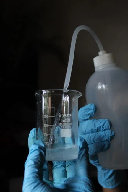
The pretreatment train should assign one job to each unit: segregate contaminants at source, equalize variable flows, remove oil and floatable material, remove settleable or flocculated solids, and prepare water for the selected biological or polishing process. The correct sequence depends on the dominant pollutant and on the waste inventory; a single “incinerator wastewater” flow figure is not a design basis.
Source control comes first because preventing contamination is usually less equipment-intensive than recovering it later. Equalization then reduces hydraulic and constituent shocks. For oil and grease removal, route the relevant stream through an oil-recovery or dissolved-air flotation duty. The industrial wastewater DAF system published by HydropureWater is intended for suspended solids, FOG, oil and grease and colloidal matter; its catalogue states a capacity range of 4–300 m³/h across 13 models and automatic skimming.
Clarification is a separate function. Lamella clarification is suited to flocculated solids after suitable conditioning, while DAF can remove floatable material as well as part of the solids load. HydropureWater’s catalogue describes its lamella clarifier as combining sludge recirculation, flocculation and inclined-plate separation in one structure. The same catalogue gives a published surface-loading range of 20–40 m/h and states that chemical consumption is reduced by up to 30%. These published values identify catalogue capability; final hydraulic sizing still requires the flow and solids-loading data collected at the site.
Chemical treatment should be defined by chemistry, not by catalogue language. The Remediation Journal treatment framework emphasizes appropriate unit operations and new chemistry for halogen- and heavy-metal-bearing incinerator waste. Where analysis indicates soluble metals requiring precipitation, establish the required pH, coagulant, flocculant or specialty reagent through jar or pilot testing. Use the automatic chemical dosing system only after those tests establish dose, mixing, control response and residual-management requirements.
| If the dominant condition is… | Preferred pretreatment function | Equipment decision |
|---|---|---|
| Free oil, FOG or floatable material | Source segregation, equalization and oil removal | Assess DAF with automatic skimming; verify oil characteristics and sludge capture. |
| Colloidal or flocculable solids | Coagulation, flocculation and solids separation | Assess DAF or lamella clarification against measured solids, settleability and required chemical demand. |
| Soluble metals requiring removal | pH adjustment and chemical precipitation | Establish chemistry through testing; define solids separation and sludge capture downstream. |
| Variable flow or batch discharges | Equalization and controlled feed | Specify turndown, mixing, level control and upset capacity using measured flow data. |
| Residual solids from chemical treatment or biological treatment | Thickening and sludge dewatering | Use a plate and frame filter press where its catalogue range—1–500 m² filter area—fits the required batch size and handling mode. |
Sludge handling closes the pretreatment loop. HydropureWater’s plate-and-frame filter press catalogue offers manual, hydraulic and fully automatic PLC operation across a 1–500 m² filter-area range. Selection must follow expected solids generation, dewatering frequency, cake route, filtrate return and operator access. Do not describe sludge as “handled” until its chemical classification, destination and acceptance route are known.
Select Biological Treatment or Membrane Polishing
MBR and UF serve different design functions: MBR combines biological treatment with membrane separation, while UF is principally a solids-barrier polishing step after upstream treatment. Neither can be selected from turbidity alone. COD, BOD, pH, toxicity, temperature, conductivity and constituent-specific data determine whether biological treatment is suitable and whether the selected membrane can tolerate the feed.
HydropureWater’s catalogue describes its MBR wastewater treatment system as activated-sludge treatment combined with submerged PVDF membrane filtration below 1 μm, with a published capacity range of 10–2,000 m³/day. Use an MBR when the treatment objective requires biological conversion and membrane separation in an integrated footprint, and when the wastewater has suitable biodegradability and membrane compatibility. That suitability must be demonstrated by analysis and, where needed, testing; the catalyst-free claim that incinerator effluent is “biodegradable” is not sufficient.
UF is the alternative where upstream clarification and biological treatment, if needed, have already produced a low-solids stream and the remaining requirement is a physical solids barrier. HydropureWater’s UF catalogue states 0.03 μm PVDF membranes, a handling rate of 2,000–40,000 L/h, inlet turbidity up to 300 ppm, and automatic backwash and air scour. These are catalogue limits, not proof that every incinerator wastewater can be fed directly to the membrane.
| Decision condition | Preferred route | Information needed before selection |
|---|---|---|
| Biodegradable organic load plus a required solids barrier | MBR | COD, BOD, toxicity, pH, temperature, conductivity, mixed-liquor behavior and membrane-fouling constituents. |
| Low-solids water after clarification and optional biological treatment | UF polishing | Turbidity, suspended solids, particle characteristics, conductivity, temperature and required permeate quality. |
| Variable concentrations, inhibitory chemicals or uncertain biodegradability | Chemical pretreatment followed by an evaluated biological or physical route | Constituent profile, toxicity assessment, jar or pilot results and treatment-train mass balance. |
| Reuse, evaporation or zero-liquid-discharge objective | Clarification plus biological treatment and membrane polishing as analysis requires | Receiving-route criteria, recovery performance, concentrate fate and pretreatment requirements. |
The Remediation Journal source specifically calls out the need to establish design concepts and chemistry for rotary-kiln wastewater containing halogens and heavy metals. That supports a staged verification approach: characterize the stream, test the proposed chemistry, then demonstrate performance on representative wastewater. Do not infer biological treatability or membrane compatibility without COD, BOD, pH, toxicity, temperature, conductivity and relevant constituent data.
Build the Pre-Specification Acceptance Checklist
A defensible equipment specification starts with measured and reconciled flow data, not a catalogue selection. Characterize normal, peak, start-up, shutdown, washdown and upset conditions, then reconcile stream flows with metered plant data where available. Identify which streams enter continuously, intermittently or only during cleanup. State whether recirculated scrubber water and dewatering filtrate are included in every flow case.
The constituent panel should cover pH, COD, BOD, TSS, oil and grease, temperature and conductivity. Add chloride and other relevant halogens, plus the metals or compounds identified by the waste inventory. For a hazardous-waste rotary-kiln installation, the waste characterization and the academic treatment framework support special attention to halogen- and heavy-metal-bearing effluent. Sampling locations must separate source streams before treatment and identify combined influent and final-effluent sampling points.
| Procurement field | Information to obtain or define before quotation | Acceptance evidence |
|---|---|---|
| Design flow | Normal, peak, start-up, shutdown, washdown and upset flows for each stream | Flow-duration record, meter reconciliation and stated sizing basis |
| Waste characterization | pH, COD, BOD, TSS, oil and grease, temperature, conductivity, relevant halogens and inventory-based metals or compounds | Laboratory reports, sampling method, preservation, detection limits and representativeness |
| Receiving route | Sewer, surface-water discharge, controlled reuse, evaporation or zero-liquid-discharge | Authority- or contract-specific limits and route confirmation |
| Equipment performance | Required removal or final quality, turndown, availability and redundancy | Worst-case duty, test protocol and acceptance tolerances |
| Chemicals and utilities | Dosing basis, storage, mixing, power, water, air and wash-water demand | Consumption schedule, utility loads and operating ranges |
| Controls and commissioning | PLC, alarms, local controls, operator access, training, trial run and included commissioning work | Control narrative, drawings, FAT or SAT scope and acceptance procedure |
| Sludge route | Expected volume and solids, cake characteristics, filtrate return, classification and disposal | Mass balance, handling method and destination acceptance |
State the receiving route before asking suppliers to define performance. Obtain the applicable site-specific acceptance criteria from the authority or contract rather than inferring them from general guidance. Use the wastewater permit and pretreatment checklist to structure permit questions, but it does not replace project-specific requirements. For evaporation or zero-liquid-discharge routes, the ZLD plant process and technology guide can support route review; the wastewater equipment specification must still identify concentrate and sludge destinations.
Before comparing bids, require test methods, sampling locations, preservation requirements, acceptance tolerances, turndown, utilities, redundancy, controls, sludge handling, operator access and included commissioning work in each offer. Normalize exclusions and guarantees. A bid that omits chemical consumption, sludge disposal or performance testing is not directly comparable with one that defines those obligations.
Frequently Asked Questions
Can DAF alone treat waste-incineration plant wastewater?
DAF can remove suspended solids, FOG, oil and grease and colloidal material, but it does not reliably remove dissolved metals or dissolved salts. It may also be insufficient for the required final effluent quality. Use it where floatables and solids are dominant, then confirm the downstream route through chemical testing and a complete constituent profile.
How should an engineer size a wastewater treatment system for a hazardous-waste incinerator?
Size from measured flow and load cases, not the nominal incinerator capacity. Provide normal, peak, start-up, shutdown, washdown and upset conditions; identify batch streams; and include recycle flows. Ask each supplier to state its sizing calculation, turndown, chemical demand, performance envelope and treatment guarantees for the governing case.
What data should a wastewater-equipment supplier receive before quotation?
Send a source-by-source flow inventory, representative laboratory results, waste-characterization data, the receiving route and applicable limits. Include pH, COD, BOD, TSS, oil and grease, temperature, conductivity, relevant halogens and inventory-based metals or compounds. Also define required test methods, utilities, controls, sludge handling and commissioning boundaries.
When is MBR more suitable than clarification followed by UF?
MBR is more suitable when biological conversion and membrane separation are both required and the wastewater passes a biodegradability and membrane-compatibility assessment. Clarification followed by UF is more suitable when upstream treatment already produces a low-solids stream and the remaining requirement is primarily a physical solids barrier. Use COD, BOD, toxicity, suspended solids, turbidity, pH, temperature and conductivity to distinguish these cases.
Which incinerator regulations apply to the wastewater treatment system?
Determine the applicable requirements from the facility, waste, discharge route and jurisdiction rather than treating incinerator air rules as wastewater approval. EPA’s sewage-sludge incineration guidance identifies air-emission controls and regulatory provisions for those systems, while liquid requirements depend on the receiving route. Request the authority- or contract-specific wastewater criteria and confirm permit boundaries with the environmental compliance lead.