
Define the Discharge or Reuse Decision
For an industrial effluent treatment plant in Hamburg, begin with the intended discharge or reuse route, then match the wastewater profile to the required treatment barriers. DAF can remove suspended solids, oil and grease and colloidal material, while lamella clarification supports compact solids separation. MBR is appropriate where biological treatment and membrane separation are needed, with HydropureWater systems spanning 10–2,000 m³/day. UF or RO may be required for reuse or high-quality polishing. Hamburg permit limits, sewer conditions and receiving-water requirements must be confirmed by the local authority and reviewing engineer; they cannot be established from the supplied research.
The first decision is not which package has the lowest headline price. It is whether the treated water will be discharged directly, sent to a municipal sewer, reused in part, or reused to a higher-quality standard. Each route changes the receiving destination, treatment objective, evidence required from suppliers and approval path.
Keep three requirements separate in the project brief:
- Discharge requirement: identify the receiving sewer or receiving water, the applicable indirect or direct discharge route, and the authority or reviewing engineer responsible for confirming local conditions.
- Reuse requirement: define the reuse application, such as process water, washing or another specified use, and the required product-water quality.
- Process requirement: record whether the water can return to production, must meet a separate quality specification, or must satisfy both reuse and discharge obligations.
The University of Twente’s PhD thesis, Direct nanofiltration of wastewater treatment plant effluent, identifies membrane technology, particularly nanofiltration, as a method for polishing wastewater treatment plant effluent to EU Water Framework Directive standards and for producing effluent suitable for agricultural or potable uses (University Library/University of Twente). That finding supports a general process principle: reclamation can require an additional polishing stage rather than biological treatment alone. It does not establish the Hamburg permit limit or prove suitability for a particular reuse application.
Use the same sequence as in this industrial effluent treatment plant selection method: define the route, identify the receiving destination, state the required water quality, and only then develop the treatment train. Ask the reviewing engineer to confirm which municipal sewer rules, industrial discharge conditions and water-law requirements apply to the facility.
| Decision field | Record for the project brief | Who confirms it |
|---|---|---|
| Final route | Direct discharge, indirect sewer discharge, partial reuse or high-quality reuse | Plant owner and reviewing engineer, with the relevant local authority |
| Receiving destination | Named sewer connection, receiving-water route or reuse point | Local authority, sewer operator or reviewing engineer |
| Water-quality requirement | Permit conditions, sewer conditions and reuse specification kept separate | Relevant authority and process designer |
| Treatment objective | Barrier removal required before discharge or reuse | Owner's process engineer and equipment supplier |
| Approval evidence | Permit application basis, technical documentation and commissioning acceptance criteria | Owner, reviewing engineer and permitting authority |
Characterize the Wastewater Before Choosing Equipment
Equipment selection becomes defensible only when the wastewater characterization identifies the barriers the treatment train must remove. A flow figure alone is not a sizing basis, and an average effluent concentration cannot represent production peaks or intermittent discharges.
Request the following from the facility’s production and laboratory teams:
- Flow data by stream, including average flow, peak flow, minimum flow, production schedule and any discharge from cleaning, batching or stormwater systems.
- Wastewater temperature and pH, with the sampling method and operating condition recorded.
- A representative analytical suite covering oil and grease, suspended solids, colloids, COD, BOD and process-specific contaminants.
- The source equipment, drainage area, collection system and points where wastewater streams combine.
- Any existing treatment, equalisation, sampling or flow-control arrangements.
Do not infer Hamburg-specific industrial limits from US effluent guidance. The US EPA describes its Effluent Guidelines as national regulatory standards for wastewater discharged to surface waters and municipal sewage treatment plants (US EPA, Effluent Guidelines). They are not a substitute for the applicable Hamburg or German requirements for the facility.
The wastewater profile should drive the next decision. Oil, grease and free oil point toward a separation barrier. Suspended solids and colloids require solids capture or clarification. High organic loading may require biological treatment before polishing. Process-specific contaminants must be named, because a generic COD/BOD package may not address them.
Require each bidder to identify the operating data and laboratory results used for equipment sizing. This is particularly important where a candidate treatment train combines an industrial DAF system for solids, oil and colloidal separation with biological or membrane stages. A supplier should explain how the selected equipment responds to the measured feed, not simply provide a nominal treatment capacity.
For Hamburg projects, distinguish confirmed technical facts from permit inputs. The technical facts may include measured flow, pH, COD, BOD, suspended solids, oil and grease, and temperature. The permit inputs must include the applicable discharge conditions, sewer requirements and any receiving-water criteria. The latter remain to be confirmed locally; they should not be inferred from generic international guidance.
| Input to obtain | Why it changes the selection | Evidence expected from the supplier |
|---|---|---|
| Average and peak flow by stream | Determines hydraulic loading, equalisation and peak treatment duty | Duty flow, peak-flow treatment and sizing calculation |
| Production schedule | Shows whether wastewater generation is continuous, batch-based or intermittent | Stated operating assumption and controls response |
| pH and temperature | Influences biological activity, coagulation, membrane operation and materials | Design limits and adjustment provisions |
| Oil and grease, suspended solids and colloids | Identifies the required primary separation barrier | Removal objective, basis and expected effluent quality |
| COD and BOD | Indicates organic loading and whether biological treatment is needed | Loading calculation and process-stage selection |
| Process-specific contaminants | May require a dedicated treatment or polishing stage | Contaminant-specific treatment rationale and evidence |
| Source equipment and drainage area | Defines the wastewater origin, collection conditions and applicable local context | Process flow diagram and equipment duty basis |
Use a DAF versus lamella pretreatment comparison to structure the next technical discussion, but do not use it as a substitute for site analysis. The key procurement question is simple: which measured barrier is the equipment intended to remove, and what result must the following stage receive?
Match the Main Treatment Barriers
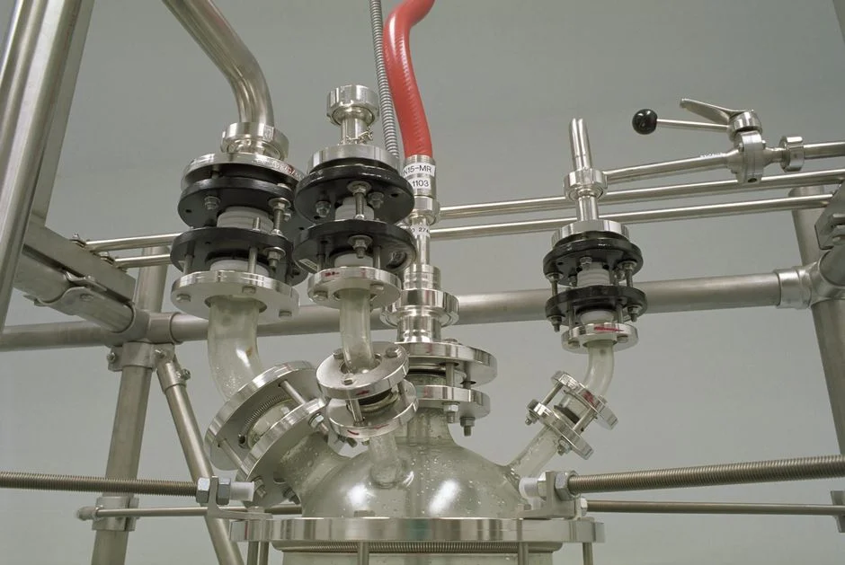
DAF is the appropriate starting barrier when suspended solids, FOG, oil and grease or colloidal material dominate the wastewater, while lamella clarification is relevant when compact solids separation and sludge recirculation are priorities. The decision should follow the wastewater profile and required outlet quality, not a preference for one equipment type.
HydropureWater states that its DAF systems cover 4–300 m³/h across 13 standard models (HydropureWater, Dissolved Air Flotation System product information). Ask the supplier to reconcile that catalogue range with the facility’s measured peak flow, hydraulic losses, equalisation and required operating margin. For a defensible basis, use the approach in DAF capacity sizing for an assembly plant, while replacing all site-specific inputs with Hamburg project data.
Consider lamella clarification when the project needs a compact solids-separation stage with sludge recirculation. HydropureWater states surface loading rates of 20–40 m/h (HydropureWater, lamella clarifier product information). Those rates should be checked against the selected geometry, feed characteristics and supplier duty calculation; they are not a substitute for clarification of solids and sludge-handling requirements.
Consider MBR where biological treatment and membrane separation must be combined. HydropureWater states that its systems cover 10–2,000 m³/day and produce near-reuse-quality effluent at less than 1 μm filtration (HydropureWater, MBR Membrane Bioreactor Wastewater Treatment System product information). Review an integrated MBR wastewater treatment system against the actual COD/BOD load, membrane pretreatment, flux, cleaning, controls and acceptance tests. Product capacity alone does not demonstrate suitability for the wastewater.
Use UF as a membrane-polishing or pretreatment stage where bacteria, colloids and suspended solids must be removed. The supplied HydropureWater catalogue range is 2,000–40,000 L/h, with 0.03 μm PVDF membranes and tolerance up to 300 ppm turbidity (HydropureWater, UF product information). Confirm feed compatibility and required residual turbidity during design.
Use RO when the reuse specification requires a higher-quality permeate. HydropureWater states recovery rates of up to 95%, subject to feed analysis and application-specific design (HydropureWater, RO product information). The supplier must state the feed assumptions, reject quality, recovery basis and pretreatment required for that rate.
A 2023 review in Environmental Engineering Research reports more than 90% microplastic removal in wastewater treatment plants, while also stating that these plants are not specifically designed for that purpose (Environmental Engineering Research, 2023). Do not convert this into a universal microplastic-removal guarantee for the proposed Hamburg plant.
| Treatment option | Use when the principal barrier is | Verified equipment scope | Supplier evidence to request |
|---|---|---|---|
| DAF pretreatment | Suspended solids, FOG, oil and grease or colloidal matter | HydropureWater states 4–300 m³/h across 13 standard models | Duty calculation, feed-water basis, separation performance and sludge handling |
| Lamella clarification | Solids separation where compact equipment and sludge recirculation are priorities | HydropureWater states surface loading rates of 20–40 m/h | Clarifier calculation, selected area, sludge recycle arrangement and solids outlet |
| MBR wastewater treatment | Biological treatment combined with membrane separation | HydropureWater states 10–2,000 m³/day and filtration below 1 μm | Organic loading, membrane design, cleaning cycle, controls and commissioning tests |
| UF membrane filtration | Bacteria, colloids and suspended solids requiring membrane polishing or pretreatment | HydropureWater states 2,000–40,000 L/h, 0.03 μm PVDF membranes and tolerance up to 300 ppm turbidity | Feed-water envelope, flux basis, backwash and residual-quality criteria |
| RO | Higher-quality permeate for the defined reuse application | HydropureWater states recovery up to 95%, subject to feed analysis and application-specific design | Feed analysis, recovery calculation, reject management and pretreatment requirements |
Build a Supplier-Ready Equipment Brief
A comparable equipment brief must state the treatment objective and the design basis before asking for a price. It should let each supplier demonstrate how the proposed package addresses the same wastewater, route, capacity and acceptance criteria.
Complete the following project fields:
- Design flow and peak flow: include the flow basis for each treatment stage and any equalisation assumptions.
- Wastewater analysis: attach representative laboratory results with sampling dates, locations and operating conditions.
- Source and drainage: identify source equipment, streams, drainage area, collection system and existing pretreatment.
- Required effluent uses: state discharge, reuse or combined objectives and the confirmed water-quality conditions.
- Utilities: provide available power, water, compressed air, drainage, chemicals and their connection constraints.
- Installation constraints: include building or plant-layout limits, access, foundations, bunding and available floor loading information.
- Operator capability: state the preferred skill level, control-system experience and available maintenance resources.
Ask each supplier to provide a process flow diagram, duty basis, equipment sizing calculation, materials of construction, control philosophy, utility requirements, maintenance plan, FAT or SAT scope, and commissioning acceptance criteria. The offer should identify which equipment performance is calculated, which is guaranteed, and which depends on site inputs or pretreatment.
Request separate lists of client inputs and third-party inputs. Client inputs should include process data, utility availability and layout information. Third-party inputs should include confirmed sewer or discharge conditions, additional sampling, utility capacity confirmation and building or plant-layout checks. This prevents permit uncertainty or missing data from being hidden inside a fixed price.
Evaluate offers in a sequence: treatment fit first, capacity basis second, removal or recovery requirements third, lifecycle and operating evidence fourth, and commercial terms last. Ask for the operating data and laboratory results behind each performance statement. The industrial ETP buyer’s decision guide provides a comparable structure for turning the route and wastewater profile into an offer basis.
| Brief field | Fillable project entry | Required supplier response |
|---|---|---|
| Treatment route | Direct discharge / indirect discharge / partial reuse / high-quality reuse | Proposed process flow and mapping to each objective |
| Design basis | Average flow, peak flow, wastewater analysis and operating schedule | Stage-by-stage duty and sizing calculation |
| Effluent requirement | Confirmed permit, sewer and reuse conditions | Guaranteed parameters, test method and sampling point |
| Equipment scope | Pre-treatment, biological, clarification, membrane and polishing stages | Equipment list, materials, controls and accessories |
| Utilities and installation | Supply capacities, connections, access and layout constraints | Utility demand and installation prerequisites |
| Verification | Acceptance tests and operating targets | FAT/SAT scope, commissioning tests and handover evidence |
| Commercial basis | Scope boundary, exclusions and requested quotation | Itemized price, schedule, warranty and lifecycle assumptions |
Frequently Asked Questions
What inputs are needed to size an industrial effluent treatment plant in Hamburg?
Provide average and peak flow by stream, the production schedule, pH, temperature, representative oil and grease, suspended solids, colloids, COD, BOD and process-specific contaminant results. Also include source equipment, drainage area, the final discharge or reuse route, available utilities and installation constraints. Ask the supplier to show which of these inputs was used for each stage’s sizing calculation.
How should a buyer compare treatment suppliers without relying on headline price?
Require the same evidence from every bidder: a process flow diagram, duty basis, sizing calculations, materials, controls, utilities, maintenance plan, FAT or SAT scope and commissioning acceptance criteria. Then compare treatment fit, capacity basis, guaranteed removal or recovery requirements and operating assumptions. Request itemized pricing so exclusions and third-party inputs remain visible rather than being buried in the total.
Which Hamburg permits and discharge conditions still need local confirmation?
Confirm the applicable municipal sewer rules, industrial discharge conditions and water-law requirements with the relevant Hamburg authority, sewer operator and reviewing engineer. The supplied research does not establish current Hamburg-specific discharge limits, so a supplier’s generic compliance statement is not enough. Put confirmed conditions and their source into the final equipment specification and acceptance criteria.
When should DAF, MBR, UF or RO be included in the treatment route?
Use DAF pretreatment when solids, oil and grease or colloids are dominant barriers. Consider MBR where biological treatment and membrane separation must be combined. Use UF for membrane polishing or pretreatment where bacteria, colloids and suspended solids must be removed, and RO where the reuse specification requires a higher-quality permeate. The final selection still depends on the measured wastewater analysis and confirmed effluent requirement; no supplied source provides a verified Hamburg price or a universal local discharge limit.