Separate the wastewater streams before selecting equipment
A Nilüfer data center should specify four separate wastewater streams because their flow patterns, chemistry, and disposal routes differ: continuous cooling-tower blowdown, sanitary wastewater, construction or commissioning wastewater, and drained or flushed liquid-cooling fluid. The supplied 2026 Istanbul guide identifies equalization, DAF or lamella clarification, multi-media filtration, UF, and usually RO as the typical open-cooling train, but its figures are transferable only as preliminary design evidence. Nilüfer-specific flows, water analyses, sewer conditions, and permit limits remain unverified. The project engineer should therefore use the matrix below to define separate equipment schedules, treatment objectives, and final-use assumptions for each stream.
Cooling-tower blowdown is a continuous stream whose composition depends on makeup water, concentration cycles, treatment chemicals, corrosion products, and drift. Sanitary wastewater requires a biological treatment basis rather than clarification and membrane recovery alone. Construction and commissioning water may contain washwater, pipe debris, cement residues, or cleaning chemicals, so each batch must be characterized before a common treatment route is assigned.
Closed-loop and immersion systems reduce continuous evaporation but do not eliminate wastewater. The supplied Valicor source states that closed-loop systems require initial filling, flushing, draining, cleaning, and refilling; their maintenance fluid may contain glycol, corrosion inhibitors, suspended solids, or dissolved metals. These streams should be batch-isolated and assessed for pH, conductivity, metals, glycol, and treatment chemicals before discharge or reuse is considered.
| Design stream | Flow pattern | Selection basis | Required site data |
|---|---|---|---|
| Cooling-tower blowdown | Continuous | Cooling chemistry, concentration cycles, and intended tower reuse | Daily flow range, temperature, pH, conductivity/TDS, TSS, metals, silica, residual biocide, antiscalant, and discharge or reuse point |
| Sanitary wastewater | Continuous or diurnal | Hydraulic load, biological treatment requirements, and permitted reuse or sewer route | Average and peak flow, wastewater COD/BOD, TSS, nutrient and pathogen basis, reuse destination, and sewer acceptance conditions |
| Construction or commissioning wastewater | Intermittent batch | Origin-specific contaminants and disposal acceptance | Batch volume, pH, TSS, conductivity, metals, cleaning chemicals, and proposed receiving point |
| Liquid-cooling drain, flush, or spent coolant | Intermittent batch | Coolant identity, glycol, metals, inhibitors, and segregability | Batch volume, glycol type and concentration, dissolved metals, suspended solids, pH, inhibitors, and whether recovery is feasible |
Use the supplied data center blowdown treatment train comparison to develop these schedules. Do not combine sanitary and cooling streams merely because they eventually reach the same sewer; the receiving constraints and treatment objectives remain different.
Estimate blowdown with site-specific cooling data
Cooling-tower blowdown should be calculated from the selected cooling architecture, not from the data-center electrical load alone. The supplied 2026 Istanbul guide gives the relationship B = E / (CoC − 1), where E is evaporative loss: at CoC 4, blowdown equals 25% of makeup, while at CoC 6 it falls to 20%. It also reports that approximately 70–80% of makeup evaporates and 20–30% leaves as blowdown. These percentages must be checked against the actual cooling-system configuration and operating data.
The same guide gives two preliminary cases. At WUE 1.8 L/kWh, a 20 MW site requires approximately 720,000 L/day of makeup and produces approximately 180,000–220,000 L/day of blowdown at CoC 5–6. A 100 MW campus requires approximately 3,600,000 L/day of makeup and approximately 900,000–1,100,000 L/day of blowdown. These are Istanbul examples supplied in the 2026 guide, not Nilüfer design values. For the Nilüfer budget, calculate each case using the project’s actual IT load, WUE, CoC, operating schedule, and expansion plan.
The guide also identifies drift of approximately 0.02% of circulation rate in the makeup-water calculation. Include measured drift, if available, rather than assuming the example value. The design worksheet should then test low-, normal-, and high-load conditions so that clarification, filtration, membranes, equalization, and reject handling are not sized from an average that conceals a peak.
| Preliminary calculation | Input | Result or procurement use |
|---|---|---|
| Makeup water | Electrical load, WUE, operating hours | Use the confirmed site inputs; compare against the supplied Istanbul examples without transferring their site conditions to Nilüfer. |
| Blowdown | Evaporative loss E and CoC | Calculate B = E / (CoC − 1), then apply the confirmed operating and future-density cases. |
| Drift | Circulation rate and measured drift | Add drift to the makeup balance; the supplied 2026 Istanbul guide uses approximately 0.02% of circulation as an example. |
| Equipment flow | Blowdown flow plus equalization and operating strategy | Determine continuous treatment capacity, batch holding requirements, and whether parallel trains are needed. |
| RO balance | Permitted recovery | Calculate product reuse and reject volume; do not assign final recovery until local discharge constraints are verified. |
Use the supplied data center wastewater reuse versus discharge analysis as a calculation reference, but keep every Nilüfer input visible in the issue register.
Match each stream to the required treatment train
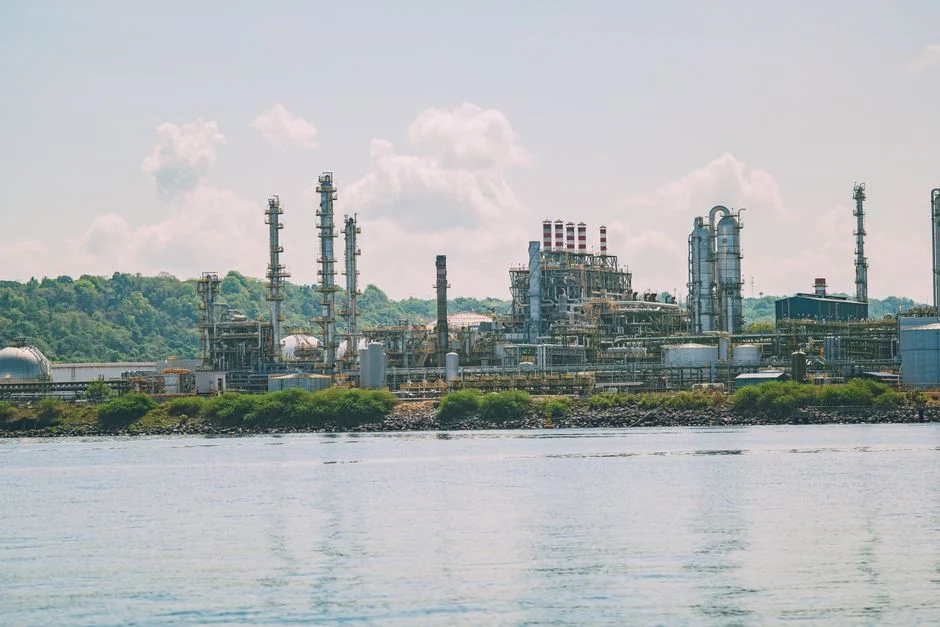
Variable cooling blowdown normally requires equalization followed by DAF or lamella clarification, multi-media filtration, UF, and usually RO when the recovered water will return to the cooling tower. The supplied 2026 Istanbul guide identifies suspended solids, oil, and flocculated metal hydroxides as reasons to select DAF before filtration. For equipment review, compare a cooling blowdown DAF system against a lamella separator using feed variability, solids character, footprint, and operating control requirements.
The supplied Istanbul guide describes a DAF capacity range of 4–300 m³/h and a UF range of 2,000–40,000 L/h per skid. Its UF configuration uses 0.03-micron PVDF membranes, feed turbidity up to 300 ppm, automatic backwash, and air scour. The same source identifies typical blowdown conditions at CoC 5–6 of 1,500–3,000 ppm TDS, pH 7.5–9.0, silica 20–80 mg/L as SiO₂, and temperature 30–40°C. These values are design-screening conditions from the 2026 guide, not confirmed Nilüfer influent limits.
Multi-media filtration should reduce suspended and colloidal load before UF, while its stated role in the supplied guide is to protect downstream RO through an appropriate SDI. A UF pretreatment for data center blowdown should therefore be selected for feed chemistry, flow variability, membrane cleaning, and permeate integration—not simply by nominal flow.
| Treatment option | Use when | Key selection checks | Principal reject or residual |
|---|---|---|---|
| Equalization | Blowdown chemistry or flow varies materially | Mixing, holding time, temperature control, and downstream hydraulic response | None, but accumulated solids require sludge management |
| DAF or lamella clarification | Suspended solids, oil, or flocculated metals must be removed before filtration | Feed variability, particle loading, chemical conditioning, and footprint | DAF or lamella sludge |
| Multi-media filtration | Colloidal and suspended solids would overload UF | Influent turbidity, SDI objective, backwash waste, and media configuration | Backwash waste |
| UF pretreatment | RO requires a controlled membrane feed | Feed turbidity, temperature, flux basis, backwash, air scour, and redundancy | Backwash waste |
| RO recovery | Treated blowdown will return to the cooling system | Scaling species, feed envelope, recovery target, antiscalant, energy, and reject route | Concentrated reject |
| MBR | Sanitary wastewater requires biological treatment before reuse or discharge | Flow, organic loading, membrane area, biological design basis, and final-use standard | Concentrated waste and sludge |
The supplied 2026 Open Engineering Inc life-cycle assessment found that the UF+RO reuse scenario consumed more than five times the freshwater-case energy, while improved cycles of concentration reduced blowdown and chemical consumption. That trade-off means higher recovery should be evaluated against energy use, makeup savings, chemical demand, and reject management rather than selected solely from a target recovery percentage. The supplied data center equipment decision framework provides the comparative structure for this screen.
Select the final discharge or reuse route
The preferred final route depends on verified Nilüfer permit conditions, sewer capacity, water chemistry, and the required recovery—not on the existence of an RO skid. The supplied 2026 Istanbul guide gives conventional RO recovery of 75–80% as a conservative default and identifies silica, calcium carbonate, and calcium sulfate as recovery constraints. A buyer should test that range against the actual feed and reject analysis before fixing the equipment guarantee.
Tower reuse is the direct route when product-water chemistry, conductivity, corrosion control, and makeup demand support the return. Sewer discharge is defensible only after the applicable authority and sewer operator confirm connection conditions and accept the treated stream’s salinity, temperature, metals, residual biocide, pH, and other discharge parameters. The supplied research does not establish Nilüfer-specific acceptance limits, so it cannot support a claim of direct sewer compliance.
Brine concentration and crystallization should be compared with discharge or partial reuse when a confirmed sewer restriction, site constraint, or corporate liquid-discharge objective makes those routes necessary. The supplied 2026 Istanbul guide states that brine concentrators and crystallizers can add 2–3 times CAPEX, although the supplied evidence does not provide a Nilüfer equipment price. Obtain a site-specific capital-cost and parasitic-load comparison.
The decision sequence is: confirm the intended final use; verify the applicable permit and sewer conditions; characterize the feed and reject; compare tower reuse, sewer discharge, and brine concentration; then select RO recovery only after the reject route remains feasible. The 2026 RO recovery-rate guide provides additional context for this comparison.
The 2026 Open Engineering Inc LCA also estimated an indirect water penalty of approximately 0.93 L/m³ for the wastewater train, less than 0.1% of the direct displacement benefit. In that same study, the wastewater scenario had about twice the GWP of the freshwater case. These results support a lifecycle comparison, but they do not replace a Nilüfer energy-price, carbon, and water-value assessment.
Turn the preliminary design into a procurement package
A procurement-ready package should preserve the distinction between the four wastewater streams and make every unresolved local assumption explicit. Issue separate flow and chemistry schedules for continuous blowdown, sanitary wastewater, and batch construction, flushing, or maintenance waste. Include continuous average and peak flow, batch volume and frequency, complete analyses, intended reuse or discharge point, operating scenarios, and future cooling-density assumptions.
Specify PLC-controlled dosing for pH correction, antiscalant, and biocide control only as required by the selected water chemistry and treatment strategy. Require factory testing, control narratives, membrane warranties, spare-parts lists, utility requirements, cleaning procedures, and clearly assigned local service responsibilities.
Each supplier should state guaranteed flow, feed-water envelope, recovery or rejection performance, utility consumption, cleaning requirements, reject volume, and the precise boundaries of its performance guarantees. Ask suppliers to identify any guarantee that becomes invalid outside the stated feed envelope. Include a supplier-selection check that compares the proposed DAF, UF, RO, biological, and reject-management equipment against the project’s actual chemistry and acceptance criteria rather than the Istanbul examples.
Treat the supplied Istanbul flows and chemistry as preliminary because the research does not verify Nilüfer water quality, sewer limits, tariffs, or permit conditions. The pretreatment compliance decision path can be used to structure those unresolved approvals in the issue register. Before budget approval, close the Nilüfer gaps identified in this article rather than transferring Istanbul assumptions into the equipment specification.
Frequently Asked Questions
What treatment train does a Nilüfer data center normally need?
For open evaporative cooling, the preliminary train is equalization, DAF or lamella clarification, multi-media filtration, UF, and usually RO, with recovered water returned to the tower and reject assigned to a verified route. Sanitary wastewater needs a biological route, while construction and liquid-cooling maintenance streams require batch-specific characterization before equipment is selected.
How much should the supplier size cooling blowdown equipment?
Size from site data using B = E / (CoC − 1), then include confirmed drift and operating scenarios. The supplied 2026 Istanbul guide reports approximately 180,000–220,000 L/day for its 20 MW case and 900,000–1,100,000 L/day for its 100 MW case; these are preliminary examples, not Nilüfer requirements.
When is RO justified instead of clarification and filtration alone?
RO is justified when recovered water has a defined cooling-tower reuse demand and clarification plus filtration do not meet the required product-water quality. The supplier must also guarantee recovery, reject volume, scaling control, energy consumption, and cleaning within the verified feed envelope.
Which information should be included in an equipment request to a Turkish supplier?
Request stream-by-stream flow schedules, analyses, final-use assumptions, applicable permit criteria, utility tariffs, guaranteed operating envelopes, performance boundaries, warranty scope, spare parts, factory testing, delivery schedule, and local service responsibilities. Request quotations for the specified duty and reject route; the supplied research contains no Nilüfer equipment price that can be used as a budget substitute.