SK On Battery Plant Wastewater Fingerprint by Process Unit
Lithium-ion battery manufacturing produces distinct wastewater streams containing N-methyl pyrrolidone (NMP), carbon powder, organic lipids, sodium sulfate, ammonium, and heavy metals such as nickel, cobalt, and manganese (Hydroflux, 2026). To properly specify an effluent treatment plant (ETP) for an expanded battery manufacturing facility, process engineers must isolate and characterize the hydraulic and contaminant loads coming from each distinct production step. Mixing un-segregated streams at the point of origin increases chemical consumption and leads to severe fouling in membrane units.
Cathode and anode electrode coating lines generate solvent recovery condensate and washdown water containing elevated organic loads, NMP solvent residue, and carbon black particles (Hydroflux, 2026). Cell assembly and electrolyte filling steps contribute organic carbonate solvents (such as ethylene carbonate and dimethyl carbonate), trace lithium salts (LiPF6), and fluoride ions. Electrical formation and cycling operations discharge high-concentration sodium sulfate and ammonium streams alongside dissolved heavy metals at low pH (Hydroflux, 2026). Finally, utility operations and pack assembly generate high-volume, low-contamination cooling tower blowdown and equipment cleaning rinses.
Equalization tanks homogenize these disparate waste streams over a standard retention period of 8 to 16 hours to eliminate hydraulic surges and equalize pH swings prior to chemical treatment (IIT Delhi, 2016).
| Process Unit Stream | Primary Contaminants | Key Water Quality Characteristics | Target ETP Pretreatment Stage |
|---|---|---|---|
| Electrode Coating & Washing | NMP, carbon powder, organic lipids | COD 2,000–5,000 mg/L, NMP 500–2,000 mg/L, TSS 100–300 mg/L, pH 6–8 | Air Stripping & Equalization |
| Cell Assembly & Electrolyte Filling | Organic carbonates, LiPF6, fluoride ions | COD 500–1,500 mg/L, Fluoride 50–200 mg/L, trace heavy metals | Defluoridation & Chemical Precipitation |
| Formation & Battery Cycling | Sodium sulfate (Na2SO4), ammonium, Ni/Co/Mn | Na2SO4 5,000–15,000 mg/L, Ammonium 200–800 mg/L, Metals 5–50 mg/L, pH 3–5 | Hydroxide & Gypsum Precipitation + DAF |
| Utilities & Module Cleaning | TDS, temperature, mild surfactants | High volume, low contamination, low COD | Direct Equalization / RO Feed Blend |
Stage 1 — Equalization, NMP Stripping & pH Correction
Equalization tanks operating with an 8 to 16-hour retention period provide continuous homogenization and pH stabilization to eliminate hydraulic and toxic shock loading on downstream ETP units (IIT Delhi, 2016). Diffused air systems or water sprays inside the equalization basin maintain continuous liquid movement to prevent suspended solids from settling while providing preliminary cooling for hot process streams (IIT Delhi, 2016).
Following equalization, NMP-bearing streams undergo packed-column air stripping. Removing NMP prior to biological treatment is critical because NMP concentrations exceeding 50 mg/L severely inhibit nitrifying bacteria in biological reactors. Operating the air stripper with an air-to-water ratio of 50:1 at elevated temperatures (40–50°C) strips over 90% of volatile organics into the gas phase for thermal oxidation or solvent recovery.
Acidic streams from formation and cycling operations (pH 3–5) enter a flash mixing basin for neutralization. Adding hydrated lime (Ca(OH)2) at dosages of 800 to 1,000 ppm elevates stream pH to 8–9 (IIT Delhi, 2016). Acidic or alkaline dosing is regulated by an PLC-controlled dosing system for pH, coagulation, and nutrients, which paces chemical injection according to real-time pH sensor feedback. Coagulant addition using alum at 200 to 300 ppm combined with polyelectrolyte flocculant at 0.2 ppm destabilizes colloidal suspension forces, agglomerating fine particulates into microflocs ready for physical separation (IIT Delhi, 2016).
Stage 2 — Chemical Precipitation + DAF for Heavy Metals & Sulfate
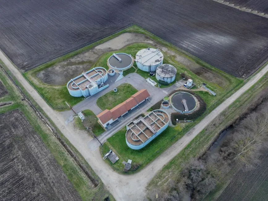
Sulfate precipitation requires calcium carbonate addition at a 5 to 90 percent stoichiometric ratio with particle sizes of 5 microns or smaller to form settleable gypsum precipitates (Hydroflux, 2026). Heavy metal contaminants present in battery manufacturing effluent—specifically nickel, cobalt, and manganese—are removed by adjusting stream pH to 9.5–10.5 using lime or caustic soda, forcing metal ions to precipitate as insoluble hydroxide sludge (Hydroflux, 2026).
Dissolved Air Flotation (DAF) separates light suspended solids, colloidal matter, and precipitated metallic hydroxides from the liquid phase by releasing micro-bubbles that attach to flocs and float them to the surface (IIT Delhi, 2016). DAF systems handle hydraulic loadings of 10–15 m/h and solids loadings of 2–4 kg/m²·h with a 20–30% pressurized recycle loop, producing a dry floated sludge containing 3–5% solids. Incorporating a heavy-duty DAF for heavy metal and sulfate precipitate removal effectively removes heavy metal flocs and gypsum crystals, protecting downstream biological membranes from scaling and physical abrasion.
| Pretreatment / Clarification Technology | Primary Removal Mechanism | Target Contaminants | Separation Footprint & Performance |
|---|---|---|---|
| Dissolved Air Flotation (DAF) | Micro-bubble flotation & surface skimming | Flocculated heavy metals, gypsum micro-crystals, free oils, TSS | Compact footprint; high loading rate (10–15 m/h); produces 3–5% solids sludge |
| Gravity Clariflocculator | Gravitational settling with slow paddle flocculation | Heavy inorganic solids, high-density metal hydroxides | Large land footprint; vulnerable to floating organic flocs; lower solids concentration (IIT Delhi, 2016) |
| Chemical Precipitation Basins | pH-driven hydroxide/carbonate precipitation | Dissolved Ni, Co, Mn, sulfate (as CaSO4), fluoride (as CaF2) | Requires sequential reaction tanks and automated dosing loops for pH control |
Stage 3 — MBR Biological Treatment: Technology Selection & Sizing
Membrane bioreactors (MBR) achieve a footprint reduction of approximately 60% compared to conventional activated sludge systems while providing sub-micron filtration for high-toxicity wastewater (IIT Delhi, 2016). Selecting MBR over conventional activated sludge (CAS) is essential for battery manufacturing ETPs due to the variable organic loading of NMP and solvents. MBR systems operate at elevated mixed liquor suspended solids (MLSS) concentrations of 8,000 to 12,000 mg/L, allowing the biological system to absorb organic shock loads without biomass wash-out.
The aerobic biological process achieves up to 90% BOD and COD removal when proper nutrient balance is maintained through controlled urea and diammonium phosphate (DAP) dosing (IIT Delhi, 2016). To meet total nitrogen (TN) limits, an pre-anoxic zone (Anoxic/Aerobic A/O process) is integrated upstream of the aeration basin with an internal recycle ratio of 200–400%. Aerobic microorganisms convert organic nitrogen and ammonia into nitrate, which is subsequently reduced to nitrogen gas in the anoxic zone.
Designing an integrated MBR system for battery plant biological treatment requires an effective food-to-microorganism (F/M) ratio of 0.05–0.1 kg BOD/kg MLSS·d, a solid retention time (SRT) of 20–30 days to sustain nitrifying bacteria, and continuous membrane air scouring (0.4–0.6 Nm³/m²·h) to control organic fouling on submerged PVDF membranes. For detailed design trade-offs between biological systems, engineers can consult our guide on MBR vs CAS comparison for high-toxicity industrial wastewater.
| Process Parameter | Conventional Activated Sludge (CAS) | Membrane Bioreactor (MBR) |
|---|---|---|
| Operating MLSS | 2,000 – 4,000 mg/L | 8,000 – 12,000 mg/L |
| Effluent Quality (TSS) | 10 – 30 mg/L (requires secondary clarifier) | <1 mg/L (sub-micron ultrafiltration barrier) (IIT Delhi, 2016) |
| Required Footprint | 100% baseline footprint | 60% footprint reduction compared to CAS (IIT Delhi, 2016) |
| Sludge Retention Time (SRT) | 5 – 15 days | 20 – 30 days (ensures complete nitrification) |
| Resistance to Organic Shock | Moderate; prone to sludge bulking | High; biomass retained by membrane barrier |
Stage 4 — High-Recovery RO + EDI Polishing for Water Reuse & Lithium Recovery
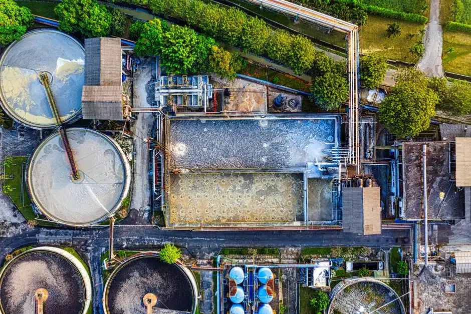
Reverse osmosis membranes effectively concentrate lithium in aqueous solutions, minimizing the necessary footprint and thermal energy requirements of downstream evaporation and crystallization systems (Hydroflux, 2026). To maximize water loop closure in battery gigafactories, tertiary treatment integrates membrane filtration skids capable of recovering over 90% of permeate water for plant re-use while concentrating sodium sulfate and lithium in the retentate.
Prior to RO desalination, MBR effluent passes through hollow-fiber ultrafiltration (UF) modules. Utilizing a UF pretreatment protecting RO membranes removes fine colloidal matter, suspended solids, and microorganisms without chemical coagulants, yielding a Silt Density Index (SDI) below 3.0 and treating turbidities up to 300 ppm (IIT Delhi, 2016).
The filtered water feeds a two-stage high-recovery reverse osmosis unit equipped with low-fouling polyamide elements. Operating a high-recovery RO for water reuse and lithium concentration achieves rejection rates exceeding 99.5% for sodium sulfate and over 99% for lithium ions, yielding high-quality permeate. To produce ultra-pure water required for cathode washing and electrolyte preparation, RO permeate is polished using an EDI polishing for ultrapure battery-grade water skid. Continuous electrodeionization eliminates the chemical hazardous waste generation associated with traditional mixed-bed ion exchange regeneration, consistently delivering water resistivity above 16 MΩ·cm.
| Membrane Stage | Membrane Configuration / Type | Primary Operational Function | Key Performance Benchmark |
|---|---|---|---|
| Ultrafiltration (UF) | 0.03 μm submerged/pressurized PVDF | Pretreatment for RO; colloidal and pathogen removal | SDI < 3.0; turbidity < 0.2 NTU (IIT Delhi, 2016) |
| High-Recovery RO | Low-fouling polyamide spiral wound | Desalination, lithium concentration, sodium sulfate separation | 90–95% water recovery; >99% solute rejection (Hydroflux, 2026) |
| Electrodeionization (EDI) | Ion-exchange membranes with continuous DC field | Ultrapure water polishing for battery manufacturing processes | Resistivity >16 MΩ·cm; zero chemical regeneration waste |
Sludge Management & ZLD Integration
Mechanical sludge thickeners increase solids concentration from a 60% water / 40% solids influent to a 40% water / 60% solids cake through high-speed centrifugal separation (IIT Delhi, 2016). Dewatering chemical and biological sludge generated during battery manufacturing is critical for controlling hazardous waste transport and disposal costs.
Chemical precipitates from Stage 2 (containing nickel, cobalt hydroxides, and calcium sulfate) are sent to a sludge thickener before mechanical dewatering. Implementing a heavy-duty filter press for all sludge streams dewatering processes both chemical solids and waste activated sludge from the MBR, forming dense filter cakes with 35–45% dry solids content suitable for off-site metals recovery or secure landfilling.
The RO concentrate stream—carrying between 50,000 and 100,000 mg/L total dissolved solids (TDS)—represents 5% to 10% of the initial raw influent volume. To achieve zero liquid discharge (ZLD), this concentrated brine is fed into a Mechanical Vapor Recompression (MVR) evaporator coupled with a crystallizer. Crystallized sodium sulfate salt can be recovered for industrial reuse, while distilled condensate returns to the plant process water reservoir. Process engineers designing zero-discharge facilities can evaluate structural frameworks detailed in our overview of CATL Germany gigafactory wastewater engineering guide and the CATL Texas battery factory wastewater framework.
Korean Regulatory Compliance Checklist for 2026
Korean Ministry of Environment (MOE) regulations under the Water Environment Conservation Act establish strict effluent discharge standards for industrial facilities operating in Special Management Areas. Designing an ETP treatment sequence for battery expansion projects requires verifying that combined discharge parameters comply with regional limits, toxic substance thresholds, and quarterly Whole Effluent Toxicity (WET) testing requirements.
Securing a formal "Water Reuse Facility" permit from local authorities allows plants to reuse over 95% of treated effluent on-site, significantly reducing total volumetric discharge, lowering municipal water intake fees, and simplifying environmental permitting procedures.
| Regulated Parameter | Korean MOE Standard (Special Areas, 2026) | Design Effluent from Stage 4 (RO + EDI) | Compliance Strategy |
|---|---|---|---|
| Biochemical Oxygen Demand (BOD) | < 10 mg/L | < 2 mg/L | Biological oxidation in MBR (IIT Delhi, 2016) |
| Chemical Oxygen Demand (COD) | < 30 mg/L | < 5 mg/L | MBR bio-treatment + RO barrier |
| Total Suspended Solids (TSS) | < 10 mg/L | < 1 mg/L | Sub-micron MBR filtration (IIT Delhi, 2016) |
| Total Nitrogen (TN) | < 20 mg/L | < 5 mg/L | A/O Denitrification loop with 300% recycle |
| Fluoride (F-) | < 10 mg/L | < 1 mg/L | Lime defluoridation + RO polishing |
| Heavy Metals (Ni, Co, Mn, Cu) | Ni < 0.5 mg/L, Cu < 1.0 mg/L | Non-detectable | pH 10 Hydroxide precipitation + DAF + RO |
Frequently Asked Questions
What parameters determine the CAPEX and OPEX for an expanded battery plant ETP featuring MBR, RO, and ZLD?
ETP capital costs depend directly on hydraulic design capacity, daily peak organic/salt loads, and the target ZLD water recovery percentage. Buyers must evaluate full equipment scope—including balancing tanks, air strippers, chemical dosing systems, MBR membrane modules, two-stage RO skids, EDI stacks, and MVR thermal crystallizers—alongside operational utility costs (electrical consumption per m³ treated and chemical consumption for lime, coagulants, and membrane CIP cycles) to build an accurate plant lifecycle budget (IIT Delhi, 2016; Hydroflux, 2026).
What equipment lead times and sizing inputs must procurement leads request when specifying MBR and RO skids?
Procurement teams should request detailed hydraulic design basis curves, membrane flux rates (LMH), maximum salinity/TDS tolerances, and complete mechanical skid dimensions. Typical manufacturing lead times range from 8 to 12 weeks for DAF clarifiers, 12 to 16 weeks for skid-mounted RO units, 16 to 20 weeks for integrated MBR systems, and 24 to 30 weeks for heavy MVR crystallizer equipment. Sizing specifications must be verified against worst-case raw effluent flow rates and concentration spikes before purchase orders are finalized.
Can RO concentrate containing sodium sulfate and lithium be routed to off-site refiners instead of on-site ZLD evaporators?
Yes, routing RO concentrate to off-site refining facilities is feasible when the concentrated stream maintains sufficient lithium density and local metallurgical recyclers accept high-sulfate liquid feeds (Hydroflux, 2026). Offloading retentate eliminates the capital expenditure of on-site thermal crystallizers, though it requires long-term off-take agreements and ongoing liquid transport logistics.
How does the treatment train accommodate sudden spikes in NMP concentrations during electrode coating washdowns?
High NMP spikes are dampened by the 8-to-16-hour equalization tank, which homogenizes incoming concentration surges prior to chemical and biological processing (IIT Delhi, 2016). Additionally, maintaining an MBR MLSS concentration of 8,000 to 12,000 mg/L provides biomass buffer capacity, preventing nitrifier inhibition during transient organic washdown events.