What the Raipur Data Center Must Treat
A Raipur data center needs treatment designed around separate domestic sewage, industrial or process wastewater, cooling-tower blowdown, RO reject, storm water, and once-through process water. The project should not combine these streams until their flows, chemistry, biological loads, reuse eligibility, and authorized disposal routes are verified. Cooling blowdown requires particular attention: evaporation leaves dissolved minerals in the circulating water, so controlled purging limits scale and corrosion accumulation. For Raipur, the treatment concept must also address local climate, groundwater or municipal supply variability, industrial users near the site, and the applicable Chhattisgarh pollution-control consent.
Start with a water balance rather than an equipment list. For every cooling system, record makeup-water source, evaporation, drift, blowdown, collection, and return flow. KETOS, in its article “Myths vs. Reality: Data Centers and Water Usage,” reports that evaporative cooling typically loses 70–80% of withdrawn water to evaporation and returns 20–30% as liquid discharge. That global context is not a Raipur design factor; the site balance must be calculated from operating and seasonal data.
Industrial effluent from nearby users may be considered for cooling make-up, but only a characterized stream with a defined acceptance test, reliable supply contract, and permitted use should enter the recovery train. Sewage, process wastewater, and blowdown require different treatment barriers even when their final destination is the same sewer or receiving system.
| Design stream | Principal design concern | Information required before selection |
|---|---|---|
| Domestic sewage | Organic load, pathogens, suspended solids, and variable flow | Flow, COD/BOD, TSS, nutrients, microbiology, and reuse or sewer route |
| Industrial or process wastewater | Variable contaminants, toxicity, oils, metals, or process-specific salts | Complete analysis across operating conditions and generator discharge profile |
| Cooling-tower blowdown | TDS, hardness, alkalinity, silica, suspended solids, corrosion, and biofouling | Cooling-water balance, cycles of concentration, and blowdown analysis |
| RO reject | Dissolved salts and concentrate volume | Feed and permeate analysis, recovery, and proposed concentrate destination |
| Storm water | Runoff contamination and discharge timing | Drainage map, rainfall records, containment design, and authorized outlet |
| Once-through process water | Water consumption and discharge composition | Continuous flow, temperature, chemistry, and reuse opportunity |
Map the Reuse and Discharge Options
Four project concepts should be compared before selecting a plant: discharge to an authorized external route, on-site treatment followed by discharge, partial recovery of blowdown, and higher-recovery internal reuse. They have different permit exposures, capital requirements, residual streams, and operating consequences. A sewer connection is not a substitute for characterizing an industrial effluent, and an on-site recovery system is not justified until the demand, water balance, and concentrate route are known.
Genesis Water Technologies, in “Treated Wastewater for Data Center Cooling: A Practical Guide to Alternative Water Sources,” reports that advanced on-site treatment can recover 70–90% of cooling-tower blowdown, RO reject, and facility process water. It presents this as a technology range, not a guaranteed Raipur yield. The same source describes a Texas facility processing 2.5 million gallons per month, reducing municipal-water consumption by 35% and eliminating blowdown-discharge fees. That case demonstrates the operating objective of recovery; it does not establish the flow, recovery, or economics for a Raipur facility.
The final choice should depend on Chhattisgarh Pollution Control Board consent, municipal sewer or discharge conditions, the receiving-water route, source-water chemistry, and the client’s water-stewardship target. A project can also retain a hybrid arrangement: recover the highest-quality portion for make-up water while sending a controlled residual to an authorized destination. Further context is available in data-center wastewater treatment in a hot climate, but local Raipur approvals must govern.
| Option | Potential advantage | Principal constraint | Decision evidence |
|---|---|---|---|
| Authorized external discharge | Lowest on-site treatment complexity | Receiving-system capacity, sewer conditions, and consent | Written acceptance route and quality limits |
| On-site treatment and discharge | Controls specified contaminants before discharge | Residual sludge or concentrate still requires a destination | Whole-life mass balance and permit requirements |
| Partial blowdown recovery | Reduces freshwater use and discharge volume | Recovery limited by concentrate chemistry | Feed analysis, salt balance, and accepted discharge route |
| Internal make-up-water recovery | Supports water resilience and reuse objectives | Needs stringent quality control and reliable residual management | Cooling specification, recovery target, and contingency supply |
Set the Cooling-Water Quality Basis

Cooling-water quality limits must be established from the site’s makeup source, concentration cycles, heat-transfer materials, and biological-control program. Genesis Water Technologies gives the following typical cooling ranges in “Treated Wastewater for Data Center Cooling: A Practical Guide to Alternative Water Sources”: TDS of 500–1,500 mg/L, hardness below 200–400 mg/L as CaCO₃, suspended solids of 10–25 mg/L, pH of 6.5–8.5, and alkalinity of 50–200 mg/L as CaCO₃. These are design references, not universal Raipur limits.
The controlling relationships are direct. Calcium, magnesium, alkalinity, and silica determine scale potential; TDS indicates the dissolved-solids load; suspended solids promote fouling and biofilm; and pH, conductivity, chlorides, sulfates, and other aggressive ions influence corrosion. A low-TDS feed can still develop unacceptable scaling concentrations if the cooling system is operated at high cycles of concentration. Conversely, TDS alone does not establish biological acceptability or corrosivity.
Genesis also states that continuous disinfection should keep bacterial counts below 10,000 CFU/mL. The data center’s cooling-water program and Legionella risk assessment may require tighter controls. Before the process design is frozen, conduct representative sampling for conductivity, calcium, magnesium, silica, sulfate, chloride, alkalinity, TDS, TSS, turbidity, temperature, pH, and relevant biological indicators. Use operating and off-operating conditions, because a single laboratory result is not a feed-water envelope.
| Parameter | Genesis reference for cooling systems | Project determination |
|---|---|---|
| TDS | 500–1,500 mg/L | Compare with site cooling limits, cycles of concentration, and concentrate control |
| Hardness | Below 200–400 mg/L as CaCO₃ | Use source analysis to define softening, NF, RO, or chemical control |
| Suspended solids | 10–25 mg/L | Establish filtration and pretreatment criteria |
| pH | 6.5–8.5 | Confirm compatibility with materials, chemicals, and the cooling program |
| Alkalinity | 50–200 mg/L as CaCO₃ | Evaluate carbonate scale and buffering needs |
| Bacterial count | Below 10,000 CFU/mL through continuous disinfection | Check against the client’s cooling-water and Legionella program |
All reference values above are attributed to Genesis Water Technologies; the source excerpt does not provide a publication date, so it should not be presented as a 2026 Raipur regulatory requirement.
Build the Treatment Train by Contaminant
The treatment train should be assigned by failure risk: each barrier must remove or control a contaminant that threatens equipment, reuse quality, or discharge compliance. The normal sequence is screening and segregation, flow and load equalization, bulk solids or organic-load removal where required, fine filtration, dissolved-solids control where justified, chemical conditioning, and final disinfection. Not every stream requires every step.
- Segregate and equalize. Keep sewage, process wastewater, blowdown, RO reject, and storm water separate until their interactions and treatment requirements are established. Equalization protects downstream units from industrial flow and composition peaks, but it does not correct contamination.
- Remove bulk material. Screening, grit removal, clarification, or biological treatment address the specific load in the selected stream. A packaged biological unit may suit domestic sewage with a significant organic load, but industrial contaminants require an engineered loading and effluent basis.
- Apply a solids and microbiological barrier. UF is appropriate where suspended solids, colloids, bacteria, or turbidity threaten the next process or the cooling system. HydropureWater states that its 0.03-micron ultrafiltration pretreatment uses PVDF membranes and accepts turbidity up to 300 ppm. The specified value is a product limit, not evidence that every Raipur feed will meet it.
- Control dissolved solids and hardness. NF or RO is considered when hardness, TDS, silica, or other dissolved constituents prevent safe reuse. Genesis reports a 150 GPM UF/NF installation at a 10-MW facility that reduced hardness from 350 mg/L to 120 mg/L. NF is associated with lower pressure than RO and partial dissolved-solids reduction; RO provides more comprehensive removal.
- Condition the final water. Use a PLC-controlled chemical dosing skid for pH, coagulation, scale inhibition, corrosion control, or disinfection only after the base process and interlocks are defined. Dosing must be linked to flow and water chemistry, not operated as an open-loop assumption.
- Disinfect where reuse enters an open loop. HydropureWater lists its chlorine-dioxide equipment for industrial cooling loops and process wastewater. The project must still verify dosage, contact control, residual management, materials compatibility, and the client’s Legionella-control program.
Membrane and backwash residuals remain part of the design. Their volume, chemistry, sludge characteristics, storage needs, and authorized destination must be established before plant capacity is fixed. A recovery system that transfers the pollution to a concentrate line is not a complete solution.
| Contaminant or risk | Primary barrier | Monitoring or acceptance check | Residual stream |
|---|---|---|---|
| Variable solids and flow | Screening, segregation, equalization | Flow profile and solids loading | S screenings or settled solids |
| Organic load | Biological treatment or clarification | Organic loading and treated effluent analysis | Sludge |
| Suspended solids, colloids, microbes | UF | Turbidity, TSS, integrity, and microbial indicators | UF backwash |
| Hardness and dissolved solids | NF or RO | Hardness, TDS, silica, and recovery | NF concentrate or RO reject |
| pH, scale, corrosion, microbes | Controlled chemical dosing and disinfection | Dose, residual, pH, corrosion indicators, and microbial control | Chemical inventory and dosing residuals |
The broader process sequence is reviewed in cooling blowdown treatment planning in Teni, but Raipur feed chemistry must determine the final arrangement.
Control the Blowdown Scaling Limit
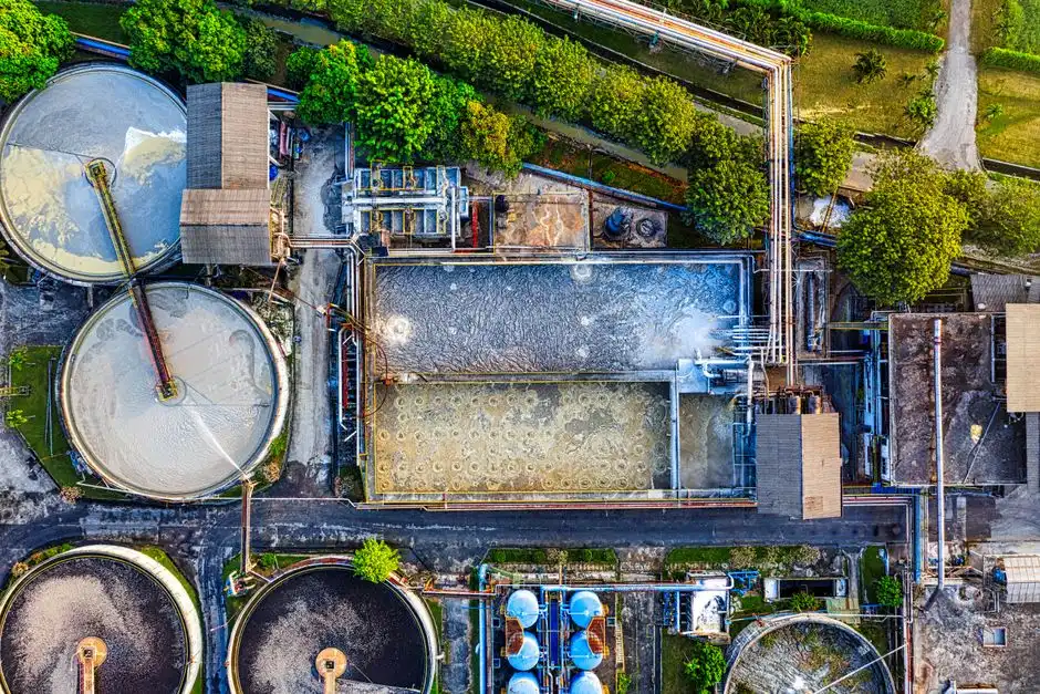
The concentrate stream, not the permeate, controls how far blowdown recovery can proceed. Evaporation concentrates silica, calcium carbonate, calcium sulfate, and other sparingly soluble constituents. As their concentrations approach saturation in the RO reject, scaling risk rises; increasing membrane pressure does not remove the underlying salt limit.
IDE Tech, in “Data Centers’ Water Reuse: Cooling Tower Blowdown,” reports that conventional brackish-water RO typically reaches 75–80% recovery before scaling becomes difficult to manage. The same source describes a specialized case operating at around 95% recovery and reducing permeate silica to about 1 mg/L by treating a difficult blended stream with a brine desalter and controlled salt precipitation. This is a reported special case, not a general design guarantee for Raipur cooling blowdown.
Higher recovery generally requires more than a larger membrane train. It can require antiscalant control, staged separation, interstage boosting, deliberate salt precipitation, concentrate recirculation, or a combination of these. Each option creates additional equipment, controls, solids handling, or residual-management obligations. The selected recovery target should therefore follow pilot work and a complete salt balance rather than a supplier’s headline recovery figure.
Require each bidder to document feed analysis, design recovery, scaling calculations, membrane flux assumptions, cleaning strategy, concentrate outlet, redundancy, and expected performance across the feed-water envelope. Also request membrane replacement assumptions, chemical consumption, shutdown provisions, and the consequences of a rejected concentrate stream. Without a compliant residual route, a high-recovery claim has little project value.
The calculation approach can be compared with data-center wastewater and cooling-blowdown treatment in Jos; only the feed chemistry and local discharge conditions determine whether the same recovery strategy is credible in Raipur.
Verify Raipur Permits and Execution Constraints
The Raipur treatment design must be coordinated with the applicable Chhattisgarh Pollution Control Board consent category, local municipal sewer requirements, industrial pretreatment requirements, and any state or local conditions governing reuse. The project team should confirm these with the responsible authorities and an Indian compliance consultant; the supplied research does not establish a Raipur-specific consent category or approval schedule.
Do not transfer overseas water-reuse figures into the local case. Genesis reports that permit applications in the jurisdictions discussed in its source can take 6–18 months, depending on jurisdiction and project complexity. That range is not a 2026 Chhattisgarh commitment and should not be used in the project schedule. The approval strategy should instead be built around a written requirement list, application inputs, reviewer meetings, and the treatment data needed for each submission.
Collect utility bills, source-water seasonal data, groundwater or municipal supply information, sewer mapping, storm-water records, power-supply reliability, and plot-access constraints. These records establish flow duration, seasonal quality, conveyance routes, redundancy, installation logistics, and operating resilience. The design review should also cover local heat and monsoon conditions, flood and earthquake resilience, odor control, noise, remote monitoring, operator competency, safe shutdown, and hazardous-chemical storage.
Permit language should define what is being discharged, where it goes, and under whose control. A contractor’s generic statement that treated water is “suitable for cooling” is not a discharge approval. The compliance basis should be reviewed alongside Indian industrial wastewater compliance requirements, then translated into project-specific obligations.
Select the Treatment System with a Decision Framework
Use a three-step decision: identify the receiving use or discharge route, select the removal barriers required for that route, and confirm recovery, redundancy, and operating requirements. This sequence prevents a preferred technology from dictating an unresolved permit or residual-stream problem.
Compare UF, NF, RO, packaged biological treatment, and chemical dosing by function, not product name. UF controls suspended solids and microbiological risk; NF targets hardness and selected dissolved constituents; RO provides broader dissolved-solids removal; biological treatment addresses biodegradable organic loads; and chemical dosing conditions water or controls residual risks. Their limitations and residual streams must be priced into the project.
The RFQ should require guaranteed flow within a stated feed-water envelope, treated-water acceptance criteria, recovery, availability, power consumption, membrane or media life, cleaning frequency, chemical consumption, residual volumes, and monitoring obligations. Performance tests should use defined sampling methods, bypass conditions, and remedies for non-compliance.
Size from verified flows using peak, minimum, startup, shutdown, and maintenance cases. Do not derive project flow from global water-use benchmarks or a generic megawatts-per-day assumption. The equipment schedule should also show tankage, backwash and concentrate storage, drain-down provisions, bypass isolation, and power-supply failure response.
| Technology | Suitable duty | Principal limitation | Residual stream | Required monitoring |
|---|---|---|---|---|
| UF | Suspended solids, colloids, and microbiological barrier | Requires suitable feed and pretreatment | Backwash | Turbidity, TSS, flow, integrity, and microbiology |
| NF | Hardness and selected multivalent-ion reduction | Does not remove all dissolved solids | NF concentrate | Hardness, TDS, silica, pressure, and flux |
| RO | Comprehensive dissolved-solids reduction | Concentrate and scaling constraints | RO reject | Conductivity, silica, hardness, recovery, and flux |
| Packaged biological treatment | Organic-load reduction in an appropriate wastewater stream | Requires verified loading and discharge basis | Sludge | Organic loading, solids, pH, and effluent quality |
| Chemical dosing | pH, coagulation, scale, corrosion, and disinfection control | Depends on monitoring and operator response | Chemical inventory and dosing residuals | Flow-proportional dose, residual, pH, and relevant control parameters |
Frequently Asked Questions
What treatment does a Raipur data center normally need?
A Raipur data center normally needs more than one treatment stream. Domestic sewage, industrial or process wastewater, cooling-tower blowdown, RO reject, and storm water have different contaminants and destinations. The final configuration depends on verified flow and analysis, the selected reuse target, residual-stream routes, and applicable Chhattisgarh and local requirements.
Should the project use UF, NF, or RO?
Use UF where suspended solids, colloids, turbidity, or microorganisms threaten downstream equipment or cooling-water quality. Consider NF when hardness and selected dissolved constituents must be reduced, and RO when broader dissolved-solids removal is required. Confirm the route against feed chemistry, recovery target, concentrate management, and the final use or discharge condition.
How should equipment sizing and supplier selection be handled?
Size from verified wastewater and blowdown flows, including peak, minimum, startup, and shutdown cases. During supplier selection, request a feed-water envelope, guaranteed flow, treated-water acceptance criteria, recovery, availability, power and chemical consumption, membrane or media life, cleaning frequency, residual-stream details, redundancy, and compliance deliverables. A technology name alone is not a defensible selection.
Can a 2026 treatment budget be quoted from the search phrase alone?
No. A responsible 2026 budget requires current wastewater and blowdown flows, source-water analyses, treatment objectives, available site utilities, the preferred recovery or discharge route, residual-management requirements, and compliance conditions. Request a budgetary quotation only after those inputs are issued as a common design basis so competing suppliers are pricing the same duty.