Why a Najafgarh Data Center Cannot Treat Blowdown as a Nuisance Stream
Cooling towers account for 20–30% of water demand at power plants, and the data-center analog — evaporative cooling — produces the same dominant wastewater stream (Open Engineering Inc., 2026). At a Najafgarh site, blowdown is therefore the design driver, not sanitary sewage. The stream carries concentrated TDS at 1,200–6,000 mg/L (4–8× makeup), suspended solids of 10–50 mg/L, scaling minerals (Ca, Mg, silica, alkalinity), residual biocides and corrosion inhibitors, plus biological content (Genesis Water Tech, 2026). A 10 million-gallon-per-month facility running at 4 cycles of concentration discharges 2.5–3 million gallons per month — a load that overwhelms municipal POTWs in a basin already stressed by groundwater overdraft (Genesis Water Tech, 2026).
Receiver sensitivity makes the local case more binding than the chemistry alone. A 2026 TNFD case study cited in the Water Utility Report confirms that mismanaged evaporative-cooling wastewater can carry elevated salts, heavy metals and pollutants, and that "the quality of the discharge matters, the treatment approach matters, and the local receiving system matters" (Water Utility Report, 2026). In Najafgarh, the ultimate receiver chain runs through the Najafgarh drain to the Yamuna, and the Delhi Pollution Control Committee (DPCC) consent regime sets site-specific effluent expectations on that corridor. If a project assumes a generic discharge path, it under-defines both the consent envelope and the design basis.
Blowdown Mass Balance: From Cycles of Concentration to a Treatable Stream
Cycles of concentration (COC) is the ratio of dissolved solids in the circulating water to dissolved solids in makeup water, and it sets both blowdown volume and blowdown quality (Genesis Water Tech, 2026). At 4 COC, blowdown equals 25–30% of makeup water; at 6–8 COC, the volume fraction drops further but TDS, silica, and corrosion byproducts climb toward the upper end of the 1,200–6,000 mg/L band, narrowing the membrane-recovery envelope and elevating scaling risk. The lever to push COC higher is side-stream filtration plus a tablet-based biocide and scale program, because liquid inhibitors accumulate in blowdown at the same factor as the salts (Genesis Water Tech, 2026).
Before any equipment is selected, anchor the project to one of two design cases. In the "reuse case," the goal is permeate suitable for cooling-tower makeup, with concentrate managed on-site. In the "discharge case," the goal is polish to DPCC consent parameters, with the remaining blowdown sent to a defined receiver. A mass balance at 4 COC, 10 MGD makeup, gives a working envelope of 2.5–3 MGD blowdown at 1,200–6,000 mg/L TDS and 10–50 mg/L TSS, which the engineer can defend in a DPCC consent meeting and which downstream sizing then inherits.
| Parameter | Value at 4 COC | Notes for Najafgarh design basis |
|---|---|---|
| Blowdown fraction of makeup | 25–30% | Drops at higher COC only if side-stream filtration is installed |
| Blowdown TDS | 1,200–6,000 mg/L | Upper bound when makeup TDS is high; governs membrane scaling |
| TSS | 10–50 mg/L | Sets the loading on side-stream filters and UF backwash |
| Biocide / inhibitor residuals | Concentrated by COC factor | Drives preference for tablet-based, non-phosphate chemistry |
| Reference facility flow | 10 MGD makeup → 2.5–3 MGD blowdown | Illustrative envelope for consent sizing (Genesis Water Tech, 2026) |
Reference 2026 Treatment Train for a Najafgarh Reuse Case
The reuse train that maps to the 4 COC envelope has four stages, and each stage has a documented performance band the engineer can defend.
Stage 1 — side-stream filtration. Treat 1–5% of circulation flow through 10–25 µm self-cleaning spiral or screen filters, CAPEX US$50k–200k for typical data-center installations, to drop suspended solids, reduce biofouling loading, and protect downstream membranes (Genesis Water Tech, 2026). Stage 2 — ultrafiltration. A hollow-fiber UF system for blowdown pretreatment at 0.01–0.1 µm, 10–30 psi, 90–95% recovery with permeate backwash, acts as the RO feed-quality barrier and as a standalone TSS and biological cap. Stage 3 — reverse osmosis. An industrial RO for cooling-tower makeup recovery at 150–400 psi, 50–85% recovery, 95–99% dissolved-solids rejection, permeate 10–50 mg/L TDS, paired with a PLC-controlled antiscalant and pH dosing skid; hybrid antiscalants combining traditional scale inhibition with catalytic action are preferred for blowdown feed (Genesis Water Tech, 2026). Stage 4 — concentrate management. The 15–50% reject is the new design problem. For most Najafgarh reuse cases, controlled blend-back of concentrate into the cooling tower is acceptable up to a permit threshold, beyond which MVC or evaporation ponds enter scope.
| Stage | Operating band | Function | Reference cost |
|---|---|---|---|
| Side-stream filtration | 10–25 µm; 1–5% of circulation | Suspended-solids and biofouling control | CAPEX US$50k–200k (Genesis Water Tech, 2026) |
| Ultrafiltration | 0.01–0.1 µm; 10–30 psi; 90–95% recovery | RO pretreatment; TSS and biological barrier | Per project sizing — request vendor quote |
| Reverse osmosis | 150–400 psi; 50–85% recovery; 10–50 mg/L permeate TDS | Dissolved-solids rejection; cooling-tower makeup | US$250k–500k for ~50,000 GPD (Genesis Water Tech, 2026) |
| Concentrate blend-back / MVC | Blend to permit threshold; MVC at 95–98% distillate recovery | Reject-stream management; on-site recovery | See ZLD section for MVC CAPEX |
When the Reuse Train Becomes a Zero Liquid Discharge Train
ZLD is justified when the discharge permit caps TDS below 1,500 mg/L, when the receiving drain is over-allocated, or when the freshwater cost breakeven closes against the recovery cost (Genesis Water Tech, 2026). The Najafgarh drain–Yamuna corridor and the DPCC consent regime are exactly the conditions where the threshold is more likely than not to be hit.
A three-stage ZLD train handles the problem in layers: RO or NF concentrates blowdown to 70–80% recovery; an MVC or brine concentrator processes the concentrate to 20–30% dissolved solids with 95–98% distillate recovery; a crystalliser processes the brine to solid salt cake, giving overall 95–99% water recovery with under 1% solid waste (Genesis Water Tech, 2026). MVC energy demand is 15–25 kWh per 1,000 US gallons of distillate, CAPEX US$1–3M for 10,000–30,000 GPD; total ZLD CAPEX US$3–8M with OPEX US$5–15 per 1,000 gallons treated. Before committing to full crystallisation, examine partial ZLD — concentrate blowdown to reduce discharge by 80–90% — which captures most of the water benefit at a fraction of full ZLD cost.
| Option | Overall water recovery | CAPEX band | Trigger condition |
|---|---|---|---|
| Reuse only (side-stream + UF + RO + blend-back) | 60–85% | Side-stream US$50k–200k; RO US$250k–500k at 50,000 GPD | DPCC consent and freshwater tariff permit |
| Partial ZLD (RO + MVC blend-back) | 85–95% | Add MVC US$1–3M for 10,000–30,000 GPD | Permit threshold restricts direct blend-back |
| Full ZLD (RO + MVC + crystalliser) | 95–99% | Total US$3–8M; OPEX US$5–15 per 1,000 gal | No liquid discharge permitted (Genesis Water Tech, 2026) |
Energy, Carbon and Water Math: Reading the 2026 LCA
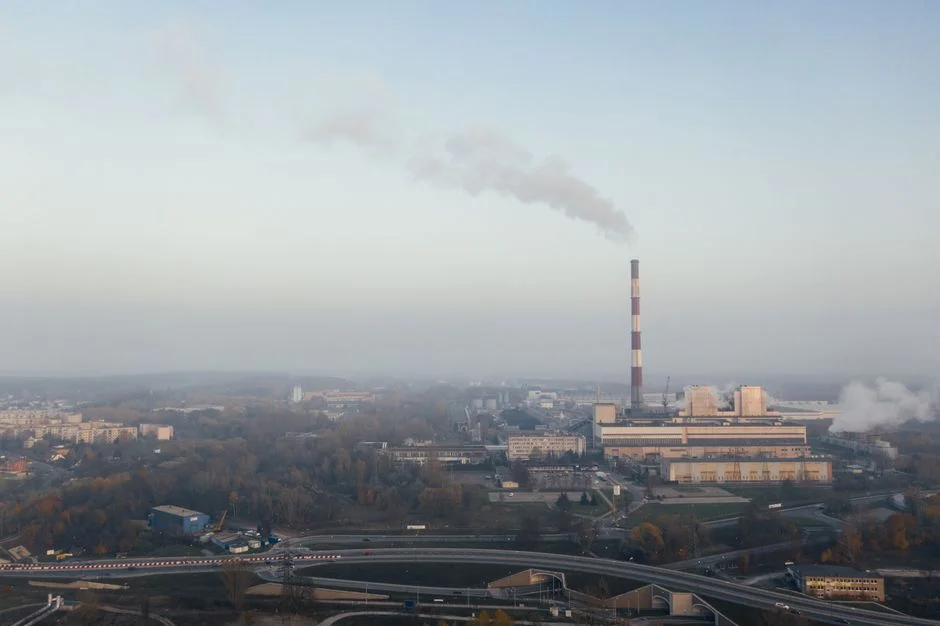
A 2026 comparative LCA finds the wastewater-reuse scenario carries about twice the GWP of the freshwater case, with treatment energy accounting for roughly 80% of that difference (Open Engineering Inc., 2026). The UF+RO train pushes reuse energy use to over 5× the freshwater case, but this is offset by higher COC that reduces both blowdown volume and chemical consumption. Run the same GWP under a fully decarbonised grid and the penalty for a system commissioned today and operated through 2050 falls to "negligible," with chemical production as the dominant residual term (Open Engineering Inc., 2026).
The water side of the ledger holds up. The indirect water penalty from upstream electricity and chemicals in the reuse train is approximately 0.93 L/m³, which is "nearly negligible, accounting for less than 0.1 percent of the direct displacement benefit" (Open Engineering Inc., 2026). In a basin like Najafgarh where groundwater overdraft and the Najafgarh jheel hydrology are active concerns, that ratio is what the engineer should carry into a Water Positive or water-stewardship claim — the energy penalty is real, the water-stewardship claim is defensible.
Decision Framework: Reuse, Discharge or ZLD for Najafgarh
Use this branch logic at the project steering committee. If DPCC consent allows TDS up to the local discharge limit and freshwater tariff is below a project-specific threshold, choose side-stream filtration plus discharge polish — lowest CAPEX, lowest OPEX. If freshwater is constrained or the project carries a Water Positive commitment, choose side-stream filtration plus UF plus RO with concentrate blend-back, expecting 60–85% blowdown recovery (Genesis Water Tech, 2026). If the receiving drain is restricted, DPCC TDS consent is below 1,500 mg/L, or the basin is water-stressed, escalate to RO plus MVC; reserve full ZLD for sites where even brine concentrate cannot be discharged (Genesis Water Tech, 2026). In every case, pair the train with a tablet-based, non-phosphate cooling-water chemistry program — liquid biocides and scale inhibitors concentrate in blowdown and will foul replacement RO and UF membrane elements or breach permit. For microbial control on the cooling loop, an on-site ClO2 generator for cooling-loop microbial control keeps residuals manageable downstream.
For a defensible 5 MW Najafgarh specification: side-stream filtration at 10–25 µm sized to 1–5% of circulation, UF at 0.01–0.1 µm as RO pretreatment, RO at 150–400 psi targeting 50–85% recovery with antiscalant and pH trim, RO concentrate blended back to the cooling tower up to the DPCC permit threshold, and MVC held in reserve as a contingency against tighter consent. This is the same architecture detailed in our Tirunelveli data center blowdown treatment guide for an Indian Tier-III context and is consistent with the 2026 cooling-sustainability solutions comparison. For non-Indian hydrology, the Konya data center blowdown guide shows the same train under a different receiver regime.
Frequently Asked Questions
What cycles of concentration should a Najafgarh data center target before sizing blowdown treatment?
Anchor the design at 4 COC, which produces 25–30% blowdown at 1,200–6,000 mg/L TDS and 10–50 mg/L TSS, then justify any move to 6–8 COC with documented side-stream filtration and tablet-based chemistry performance (Genesis Water Tech, 2026). Request a vendor water-balance worksheet tied to your specific makeup TDS before committing to a higher COC.
What does a cooling-tower blowdown reuse train cost in 2026?
For a 50,000 GPD RO system treating blowdown, CAPEX is US$250,000–500,000 with OPEX US$1.50–3.00 per 1,000 gallons treated; side-stream filtration adds US$50,000–200,000; full ZLD adds US$3–8M and OPEX US$5–15 per 1,000 gallons (Genesis Water Tech, 2026). Request a sized quotation rather than scaling these bands to your flow, because membrane count, energy recovery, and concentrate management dominate total cost.
When is zero liquid discharge the only defensible choice for a Najafgarh site?
When DPCC consent caps TDS below 1,500 mg/L on the Najafgarh drain–Yamuna corridor, when the basin is over-allocated, or when no liquid discharge is permitted at all, escalation to RO plus MVC and then to full ZLD with crystallisation is justified (Genesis Water Tech, 2026). Check the current DPCC consent schedule and the receiving drain's assimilative capacity before locking the train.
How do I evaluate a blowdown-treatment supplier for an Indian data center?
Require reference plants running an integrated side-stream filtration, UF and RO train on cooling-tower blowdown, documented recovery in the 60–85% band, and demonstrated experience with DPCC or equivalent state pollution control consent submissions (Genesis Water Tech, 2026). Ask for a vendor water balance that includes concentrate blend-back limits and a written position on tablet-based, non-phosphate cooling chemistry compatibility with the proposed membrane fleet.
Related Equipment
- industrial RO for cooling-tower makeup recovery — specifications, capacity range, and technical data