
What the Filter Press Process Flow Diagram Shows
A filter press process flow diagram maps the dewatering train as seven sequential blocks: sludge storage/equalization tank → chemical conditioning skid → feed pump → plate pack with filter cloths → filtrate manifold → cake discharge chute → filtrate return or clear-water outlet. The diagram must capture the upstream choice that fills the storage tank, because the line only works if the feed matches the press specification.
Conventional clarifier underflow lands at 0.6%–1.5% dry matter (DM), which is too thin for the press, so two upstream paths are common: a gravity thickener producing about 3%–4% DM, or a Dissolved Air Flotation (DAF) unit upstream of the press producing 4%–5% DM. With DAF, the intermediate thickener is dispensable (S4, Sigmadaf Clarifiers). Filter press operation is batch-wise, unlike belt or screw presses, so a cycle controller and a cake collection skip mounted under the open plate pack belong on the P&ID (S4). The recycle loop must close on the drawing: filtrate and wash water are contaminated streams and are typically returned to the head of the effluent treatment plant rather than sent to sewer, as confirmed in the polymer sludge retrofit case (S5, Processes, 2024-03). The HydropureWater plate and frame filter press line and the DAF skid above it can be drawn against this block sequence without modification.
Block 1 — Sludge Storage and Pre-Conditioning
Settled sludge from a conventional clarifier arrives at the storage tank at 0.6%–1.5% DM, well below the 3%–5% minimum feed that makes a filter press viable (S4). An intermediate thickener or a DAF unit is mandatory before the press; selecting DAF at 4%–5% DM removes the thickener from the flow and shortens the train by one block (S4). Inside the storage/conditioning tank, polymer flocculant is dosed at no more than 4 kg per tonne of dry matter, and lime can be added up to 15% of sludge DM when higher cake dryness is the target (S4). For difficult feeds, coagulants such as Fe(OH)₃ or polyaluminium chloride (PAC) are dosed ahead of the flocculant, and a diatomaceous earth skeleton builder is used on polymer-rich sludges to help cakes release cleanly from the cloth (S4; S5). The conditioning block is the single point where the dose window is set, so it is paired on the diagram with an automatic polymer and lime dosing skid whose output tracks feed solids. Because no fixed dose applies across sludge types, the bench data a buyer must obtain before specifying is a jar-test-derived dose curve on the actual sludge; this is the input that turns the conditioning block from a generic skid into a sized, defensible block on the P&ID. A DAF vs clarifier decision guide is a useful reference when the upstream path is still open.
Block 2 — Feed Pump and Plate Pack
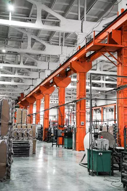
The feed pump is normally pneumatic because of the high solids content, and it is paired with a low-pressure support pump that fills the chambers quickly in roughly 5–6 minutes so cakes form uniformly (S4). Sludge enters the chambers through a central manifold that branches to each chamber, and the filter cloths on the plate faces retain the solids while filtrate drains to the opposite side (S4). Plates are typically polypropylene and range from 80×80 cm up to 250×250 cm; the chamber count is selected from the volume of sludge to be dewatered per cycle and usually falls between 12 and 50 chambers (S4). Operating pressure is about 6 bar for standard units, with high-pressure machines reaching 16 bar or more to push cake dryness higher; pressure is held by an electro-hydraulic closure unit acting through a central piston (S4). Filter cloths are made of plastic fibres — PP, polyester, polyamide — and are permeable to liquid while retaining suspended solids (S4). In a plate-frame study using cotton cloth at 4% w/w CaCO₃, the cloth selected produced 56.00% solute removal efficiency (S1, National Research and Innovation Agency). The pressing step ends with an air-blow pass that drives residual water out of the cake; cycle end is confirmed by a flow sensor on the filtrate line and a pressure-switch signal (S4). The table below summarises the operating window that a P&ID reviewer will look for on this block.
| Parameter | Typical value | Source |
|---|---|---|
| Feed pump type | Pneumatic (with low-pressure support pump) | S4 |
| Chamber fill time | ~5–6 minutes | S4 |
| Plate material / size | Polypropylene, 80×80 cm to 250×250 cm | S4 |
| Chamber count | 12–50 per press | S4 |
| Operating pressure | ~6 bar standard; up to 16 bar (or higher) for high-pressure units | S4 |
| Filter cloth fibres | PP, polyester, polyamide | S4 |
| Cycle-end signal | Filtrate flow sensor + pressure switch | S4 |
Specification requests should be sent against this table; the HydropureWater plate and frame filter press range is built to match these block parameters. Linking these mechanical specifications to the process flow ensures the equipment is sized correctly for the intended application.
Block 3 — Filtrate, Cake Discharge and Recycle
Filtrate exits on the side opposite the feed manifold and is collected in a manifold that runs the length of the pack (S4). Whether the filtrate is discharged directly or recycled to the head of the ETP depends on local limits and on whether the upstream conditioning has stripped the contaminants: in the polymer sludge retrofit, the filtrate met local discharge regulations and was disposed of without further treatment (S5, 2024-03), while in other retrofits the filtrate is returned to the front of the plant because the wash stream is contaminated (S5). Cake discharge is gravity-driven once the plate pack is decompressed: the electro-hydraulic group releases, plates separate in sequence, and cakes fall into a skip or conveyor mounted beneath the open pack (S4). For plate sizes above about 1 m, automatic plate-shifters with vibration or rapping are used; for smaller filters, manual or lever-assisted separation is acceptable (S4). Cake breakers and air-knife passes are included on the diagram because they dislodge residual cake, prevent cloth blinding, and reduce skip volume — these steps protect the next cycle (S4). A related process flow diagram guide for EGSB reactors shows a similar recycle-loop pattern that the filter press line should mirror on the P&ID.
Sizing the Press from a Daily Sludge Flow

The sizing example in S4 (Sigmadaf Clarifiers) starts with 785.7 L of sludge to dewater per day, with the operator running two 4-hour cycles per day so each batch is about 392.9 L of sludge at a target cake dryness of 30%. Chamber volume in the example is 19.7 L, so chambers needed = 393 ÷ 19.7 ≈ 19.9, rounded to 20 chambers; with the rule n+1 plates, that gives 21 filter plates and a filtration area of 20 × 1.53 m ≈ 30.3 m² (S4). The general rule is the same one the table rests on: number of chambers = batch sludge volume ÷ single chamber volume, adjusted for sludge density and the dryness achievable in a lab test on that specific sludge (S4). A 50% volume reduction with around 80% moisture in the cake is typical for conventional sludge, while fibrous sludges such as pulp and paper can reach 50%–60% dry solids in the same machine class (S5, Processes). The bench data a buyer must obtain before sizing is a lab dryness test (capillary suction time, specific resistance to filtration, or a press-cell test) on the actual sludge, because the dryness number drives the chamber count and the plate area. Once those inputs are in hand, the HydropureWater plate and frame filter press line is selected to match plate count, area, and pressure class. The UASB reactor process flow diagram guide is a useful cross-reference for the upstream solids concentration assumption that feeds this calculation. A lamella clarifier thickener option is one of the upstream choices that determines whether the 3%–5% feed condition is met at all.
Common Operator Issues in the Flow
Most filter press faults trace back to one of three blocks, and the diagram makes the diagnosis faster because the symptom points to a specific block. The table below maps the symptom to the block and to the corrective step that is supported by the research.
| Symptom | Block on the diagram | Corrective step | Source |
|---|---|---|---|
| Residual cake sticking to plates after discharge | Cake discharge / plate pack | Air-knife blow, rapping, manual cloth wash; verify no cake remains to avoid sealing failure next cycle | S4 |
| Short cycle or failure to reach design dryness | Chemical conditioning | Re-check flocculant dose (≤4 kg/t DM) and lime dose (up to 15% DM) against lab target | S4 |
| Filtrate solids breakthrough (cloudy filtrate) | Plate pack / filter cloths | Schedule closed-circuit cloth wash or remove and clean cloths manually; check cloth specification | S4 |
Each row is an operational use of the diagram rather than a service note, and each one is drawn from the same source that defined the block layout (S4, Sigmadaf Clarifiers). Consistent monitoring of these parameters prevents downtime.
Frequently Asked Questions
How is a filter press sized for a given daily sludge volume?
Divide the daily sludge volume by the number of cycles per day to get the batch volume, then divide the batch volume by the chamber volume to get the number of chambers, and add one plate per the n+1 rule (S4). A worked example using 785.7 L/day, two 4-hour cycles, and a 19.7 L chamber gave 20 chambers, 21 plates, and 30.3 m² of filtration area at 30% target dryness (S4). The input a buyer must request from a lab is the achievable dryness on the actual sludge, because that number drives the chamber count and the area.
What upstream equipment is required before a filter press?
A feed of 3%–5% DM is the minimum for the press to work, so conventional clarifier underflow at 0.6%–1.5% DM must be lifted by either a gravity thickener (3%–4% DM) or a DAF unit (4%–5% DM) (S4). With DAF upstream, the intermediate thickener is dispensable, and the line goes clarifier → DAF → conditioning → press (S4). A Dissolved Air Flotation (DAF) unit upstream of the press is the compact path when footprint is constrained.
What polymer and lime doses are typical for filter press conditioning?
Polymer flocculant is typically dosed at no more than 4 kg per tonne of dry matter, and lime can be added up to 15% of sludge DM when higher dryness is the goal (S4). These are upper-bound operating ranges, not design numbers; the dose that any specific sludge needs is set by jar tests on the actual feed. An automatic polymer and lime dosing skid is specified to track feed solids once the lab dose curve is available.
What should a buyer compare when selecting a filter press supplier?
The checks a buyer should make on a shortlist are plate count range, plate size, operating pressure class, and confirmed chamber volume