Reading a UASB Reactor Process Flow Diagram
A UASB reactor process flow diagram traces wastewater as it moves upward through four sequential zones: an influent distribution manifold that spreads feed across the reactor base, a sludge bed zone where dense granules convert organics into biogas, a three-phase gas–liquid–solid (GSS) separator that disengages biogas from the rising flow and returns sludge, and an effluent launder that carries clarified water to downstream polishing. Off the main flow, a biogas collection hood routes 65–75% CH4-rich gas to utilisation, while an effluent recycle loop lets operators control upflow velocity between 0.5–1.5 m/h. The diagram always shows a downstream polishing unit because UASB alone removes 70–85% of the original COD load (per anaerobic-digestion.com, 2026).
Reading the PFD from left to right, the influent first enters an equalisation tank, then a feed manifold at the base of the reactor, then the granular sludge bed where biological conversion occurs, then the GSS, and finally the effluent launder. Two arrows loop back on a credible drawing: an internal sludge-return inside the GSS deflectors, and an external recycle line that takes a fraction of clarified effluent back to the suction of the feed pump. The only arrow that leaves the liquid envelope is the biogas off-take from the gas hood, drawn at the top of the reactor and typically piped to a flare, boiler, or CHP unit (per anaerobic-digestion.com, 2026).
On the right-hand side, the PFD extends past the UASB shell into a downstream polishing block. This block is part of the same diagram because the UASB effluent still carries 15–30% of the original COD, plus nutrients the anaerobic step barely touches — typical removals for both nitrogen and phosphorus sit below 15% (per anaerobic-digestion.com, 2026). The polishing block is drawn as an aerobic stage, a down-flow hanging sponge (DHS), an MBR, or a constructed wetland depending on the discharge standard. Treating the polishing block as a separate plant is a common read-error; on a complete PFD it is a continuation of the same flow path.
Block 1 — Influent Distribution and Equalisation
The first block on the PFD is the distribution manifold at the base of the reactor: a header pipe with multiple nozzle branches that spread incoming wastewater across the full cross-section of the sludge bed. Without uniform distribution, feed channels preferentially through a few high-permeability paths, leaving large fractions of the bed under-loaded and starving the granules there of substrate. Distribution design and seeding density are linked — an even feed supports the 10–15 g VSS/L seeding inoculum recommended during start-up, which typically fills 20–30% of the reactor volume before the system is loaded (per anaerobic-digestion.com, 2026).
Equalisation is usually drawn just upstream of the PFD proper, but it is functionally part of Block 1. Variable influent flows would otherwise breach the 0.5–1.5 m/h upflow window that the granular bed requires to stay fluidised without being washed out (per anaerobic-digestion.com, 2026). An equalisation tank dampens both hydraulic and concentration peaks so the distribution manifold sees a near-constant load. pH correction also sits in this pre-block; the standard approach is dosing with an automatic chemical dosing system for pH correction upstream of a UASB.
If distribution is undersized, the failure mode is qualitative rather than numeric: channelling, dead zones beneath poorly placed nozzles, and granules that never contact fresh substrate. These issues are not visible on a PFD, which is why a vendor drawing should always label the number of nozzle branches and the spacing — not just the header diameter.
Block 2 — The Granular Sludge Bed
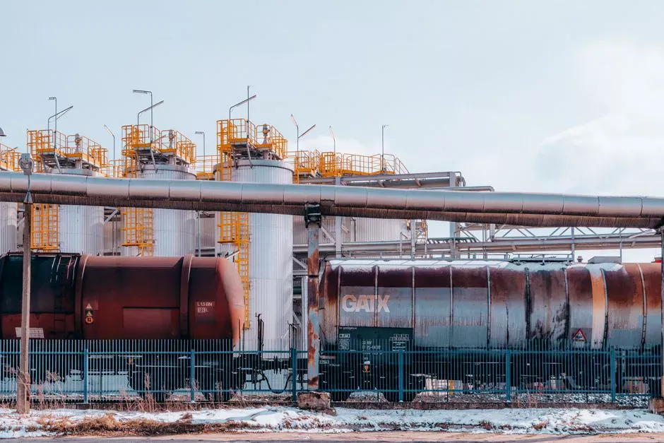
The sludge bed is the only block on the PFD where biological conversion actually happens. It is drawn as a dense layer occupying the lower 40–60% of the reactor volume in a mature system, packed with 1–3 mm granules that settle at velocities above 25 m/h (per anaerobic-digestion.com, 2026). That settling velocity is the hydraulic selection mechanism: continuous upflow washes out light, flocculent biomass while retaining dense, well-aggregated granules, so the bed self-thickens over time without mechanical screens.
The sizing logic for this block is anchored to the organic loading rate. Mature industrial UASB systems operate between 4 and 15 kg COD/m³/d, well above the 1–3 kg COD/m³/d typical of conventional anaerobic digesters (per anaerobic-digestion.com, 2026). The Zenodo refinery UASB study applied OLRs of 0.58, 0.89, 1.21 and 2.34 kg/m³·d to petroleum refining wastewater, which sits below the mature-industrial band because the granules in that study were still being acclimatised (per Zenodo, S2). When you see a vendor PFD with an OLR figure, check whether it represents the design point or an early commissioning point — they differ by an order of magnitude.
Temperature is the second sizing qualifier. Performance declines roughly 10–12% per 5°C below 20°C, so a UASB PFD must be qualified by site climate data (per anaerobic-digestion.com, 2026). For cold effluents in the 10–20°C range, the diagram is usually redrawn as an EGSB or IC variant rather than a conventional UASB.
Block 3 — Three-Phase Separator (Gas–Liquid–Solid)
The three-phase separator, often labelled GSS or GLS on a vendor PFD, is the most visually complex block on the drawing. It sits in the upper portion of the reactor and is drawn as concentric features: a central gas hood with deflection wings, a slurry return channel along the deflector walls, and an outer overflow weir feeding the effluent launder. The GSS allows gas to escape upward, sludge to slide back down, and clarified liquid to move outward — simultaneously, inside the same vessel.
The three separations are explicit on a well-drawn PFD. Biogas leaves the reactor through the gas hood at the top of the vessel; the off-gas composition is 65–75% CH4, which characterises the stream as a medium-grade fuel suitable for boiler firing or combined heat and power (per anaerobic-digestion.com, 2026). Sludge that contacts the deflector walls slides back into the bed, drawn as downward arrows on the diagram. Clarified liquid crosses the overflow weir into the effluent launder, drawn as a horizontal arrow leaving the reactor shell.
A common PFD-reading error is to assume the GSS is a reaction block. No COD removal happens inside the GSS; it is purely a separation device. The biological conversion is complete by the time mixed liquor reaches the bottom edge of the separator, and everything above that line is hydraulics. If a vendor PFD shows internal mixers, diffusers, or feed points inside the GSS zone, that is a red flag during review.
Block 4 — Effluent Launder, Recycle and Downstream Polishing
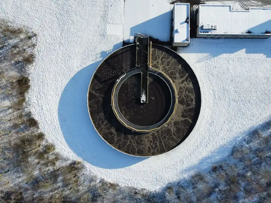
The effluent launder is the peripheral trough at the top of the reactor that collects clarified water from the GSS overflow weirs. On a PFD it is drawn as a U-shaped channel wrapping the upper rim, with a single outlet pipe leading to the next tank. That outlet is the boundary between the UASB envelope and the rest of the treatment train.
From the launder, the diagram typically splits into two streams. One fraction leaves the plant as forward flow toward the polishing block; the other fraction returns through an external recycle line to the inlet of the feed pump. The recycle exists to hold upflow velocity in the 0.5–1.5 m/h band during low-flow periods, and it can be throttled back to allow peak velocities up to 3 m/h during hydraulic surges (per anaerobic-digestion.com, 2026). If the recycle line is missing from a vendor PFD, the drawing is incomplete.
The downstream block on the PFD is mandatory because a UASB alone removes 70–85% of the original organic load, leaving 15–30% of the influent COD still in solution (per anaerobic-digestion.com, 2026). A documented pairing is the DHS down-flow hanging sponge reactor coupled upstream of a UASB for onion dehydration wastewater, as reported in Bioresource Technology (per Elsevier, S1). Aerobic stages, MBRs, and horizontal subsurface flow wetlands are also drawn at this position, with wetlands typically achieving 75–85% BOD removal on UASB effluent (per anaerobic-digestion.com, 2026). The EGSB evolution is drawn with a taller reactor and an expanded sludge zone, using 5–10 m/h upflow to improve wastewater-biomass contact (per anaerobic-digestion.com, 2026). For typical operating issues encountered after start-up, the UASB reactor common problems and solutions engineering guide covers the diagnostic sequence in detail.
UASB Process Flow Parameters at a Glance
The table below anchors the PFD to the operating envelope you should see on a vendor drawing. All values are sourced from the same reference; ranges are quoted as published and not extrapolated.
| Envelope | Parameter | Value |
|---|---|---|
| Operating | OLR (mature granular UASB) | 4–15 kg COD/m³/d |
| Operating | Upflow velocity (normal) | 0.5–1.5 m/h |
| Operating | Upflow velocity (peak) | Up to 3 m/h |
| Operating | COD removal | 80–95% |
| Physical | Granular bed fraction of volume | 40–60% |
| Physical | Granule diameter | 1–3 mm |
| Physical | Granule settling velocity | >25 m/h |
| Physical | Seeding density | 10–15 g VSS/L, 20–30% of volume |
| Resource | Energy use vs aerobic | 40–60% lower |
| Resource | Excess sludge vs aerobic | 80–90% less |
| Resource | Biogas CH4 content | 65–75% |
| Temperature | Performance loss below 20°C | ~10–12% per 5°C drop |
| Temperature | EGSB/IC cold tolerance vs UASB | Acceptable 3–5°C lower |
When the values on a vendor PFD fall outside these ranges, ask for the supporting design basis. Ranges shown here reflect mature granular systems per anaerobic-digestion.com (2026).
How to Read a Vendor PFD Before You Approve It
Seven items must appear on a credible UASB PFD before it is worth a serious review:
- Equalised feed tank upstream of the reactor
- Distribution manifold at the reactor base with multiple nozzle branches
- Granular sludge bed zone, dimensioned or at least labelled with bed fraction
- Three-phase (GSS) separator with deflection wings, gas hood, and overflow weirs
- Biogas off-take from the gas hood, with a defined utilisation node downstream
- Effluent launder with the recycle line and the forward flow line both drawn
- Downstream polishing block in scope, not relegated to a "by others" note
The most common omissions on vendor drawings are the recycle line, the sludge-return arrows inside the GSS, the biogas utilisation node, and the polishing unit. Each omission is a place where the supplier has left scope undefined, and each becomes a change-order risk during commissioning. Before signing off, ask the supplier for the design OLR, the design upflow velocity, the expected COD removal at design load, and confirmation of which downstream block sits inside their scope. EGSB and IC variants must be clearly labelled, because their geometry — taller reactor, expanded bed, internal recirculation — differs visibly from a conventional UASB drawing (per anaerobic-digestion.com, 2026). For nutrient-sensitive discharges, an MBR polishing stage downstream of a UASB reactor is the typical scope addition the PFD must then accommodate.
Frequently Asked Questions
What does a complete UASB PFD include beyond the reactor shell?
A complete PFD includes the equalisation tank, the influent distribution manifold, the granular sludge bed, the three-phase separator, the biogas
Frequently Asked Questions
What are the main components shown in a UASB reactor process flow diagram?
A standard UASB reactor process flow diagram highlights four critical zones: the influent distribution system at the base, the sludge bed/blanket zone, the three-phase separator (gas-liquid-solid separator) at the top, and the gas collection hood. Ancillary components include the influent pumping station, recirculation piping, effluent launders, and biogas handling equipment such as flame arrestors and scrubbers.
What is the difference between a UASB and an EGSB reactor on a PFD?
The primary difference on a process flow diagram is the presence of an external recirculation loop in an Expanded Granular Sludge Bed (EGSB) reactor, which is typically absent or minimal in a standard UASB. EGSB diagrams will also show a taller, more slender vessel profile to accommodate higher upflow velocities, often exceeding 6 to 10 m/h, compared to the lower vertical profile and lower velocities of a UASB.
What is the typical upflow velocity and OLR for a UASB reactor design?
In a standard UASB design, the superficial upflow velocity is typically maintained between 0.5 and 1.5 m/h to ensure proper sludge granulation and prevent biomass washout. The Organic Loading Rate (OLR) generally ranges from 5 to 15 kg COD/m³·day, depending on the wastewater characteristics and temperature conditions maintained within the reactor vessel.
How do I choose the right supplier for a UASB reactor package in 2026?
For 2026 engineering projects, prioritize suppliers who provide computational fluid dynamics (CFD) modeling for flow distribution optimization and offer modular, skid-mounted three-phase separator designs. Verify the supplier's capability to integrate digital twin monitoring for real-time sludge bed height tracking and ensure they comply with updated ISO 14001 environmental standards and local pressurized vessel certifications for biogas containment.
What downstream treatment is normally drawn after a UASB on the PFD?
The effluent from a UASB reactor is typically routed to an aerobic polishing stage, such as an Activated Sludge Process (ASP), a Membrane Bioreactor (MBR), or a Moving Bed Biofilm Reactor (MBBR), to remove residual COD and nutrients. If high-quality discharge or water reuse is required, the PFD will also include a secondary clarification unit followed by tertiary filtration, such as sand filters or ultrafiltration membranes.