What Micro Bubble Flotation Means in a Pharmaceutical Effluent
Micro bubble flotation is a dissolved-air-style separation step in which a generator produces bubbles in the tens of micrometres range, rather than the millimetre bubbles used in conventional dissolved air flotation (DAF). In a 2010 study of a TCRI-A micro-bubble generator running at 0.9 MPa, approximately 67% of the generated bubbles were below 20 µm in diameter (Sep. Purif. Technol., 2010, S2). The same study measured a total oxygen mass-transfer coefficient KLa of 1.1754 min⁻¹ for the micro-bubble reactor, versus 0.7535 min⁻¹ for a conventional air-bubble reactor under otherwise identical conditions.
Three physical consequences follow from that size shift. Smaller bubbles expose more gas–liquid interfacial area per unit gas volume, so oxygen and dissolved-gas transfer rises. The smaller diameter also lengthens residence time in the water column, so collisions with suspended particles become more likely. And the lower rise velocity is offset by the much higher bubble count delivered by the same air volume. The net effect is higher capture probability on fine particulates, which is precisely the property a pharmaceutical matrix requires for emulsified oils, fermentation cell debris, and low-density API solids.
For pharmaceutical effluent, this positions micro-bubble flotation as a primary clarification or pre-treatment step ahead of biological or membrane polishing — not a stand-alone polish. The role matches how DAF is reported for pharmaceutical residue streams when paired with an MBR (PubMed, S4). The technology does not replace secondary treatment; it conditions the stream so that downstream biology or membranes see a lower, more biodegradable load.
Why Pharmaceutical Streams Need a Micro-Bubble Step
Pharmaceutical effluent typically carries emulsified oils from formulation, organic solvents such as acetone, methanol and MIBK, spent fermentation broth with high suspended solids, and active pharmaceutical ingredients (APIs) themselves. The closest published benchmark matrices for micro-bubble flotation are oily wastewater and dyeing wastewater, not pharma — and that gap is one reason on-site jar tests are still required. The data the engineering team can lean on today comes from those two matrices.
For emulsified oil and suspended solids, the UNBC 2024 study (S1) on NB/MB gas flotation reported 98.8% oil/water separation at 1,995 mg/L initial oil, 45 minutes of gravity settling and 38 minutes of flotation (R² = 0.99). A 75 L pilot reached 92% oil removal in one hour, against 4.62% for gravity settling over the same period. The matrix is oily-spill water rather than API wastewater, but the droplet size distribution and the emulsion stability are similar to formulation rinse water.
For COD, color and oil reduction ahead of biology, the 2010 dyeing-wastewater study (S2) reported COD removal 30% higher, color 110% higher, and oil 40% higher with coagulation micro-bubble flotation than with coagulation conventional air-bubble flotation in the same reactor. The same work showed biodegradability (B/C) rising from 0.290 to 0.363 after micro-bubble flotation, against 0.301 for conventional air-bubble flotation. A higher B/C at the outlet of primary clarification directly reduces the load on activated sludge or an MBR downstream.
For variable batch streams, the UNBC 2024 work also found no significant difference in oil-separation efficiency between fresh and weathered oil (S1) — a relevant property for batch API plants that dump variable solvent and oil mixtures. NB/MB flotation is described in that work as a chemical-free separation step, which simplifies permitting where coagulant discharge is restricted. Where the plant already operates a HydropureWater DAF system, the same vessel can be re-evaluated for a micro-bubble retrofit by changing only the saturator and nozzle geometry.
Inside the Mechanism: How Micro Bubbles Capture API, Oil and Solvent Droplets
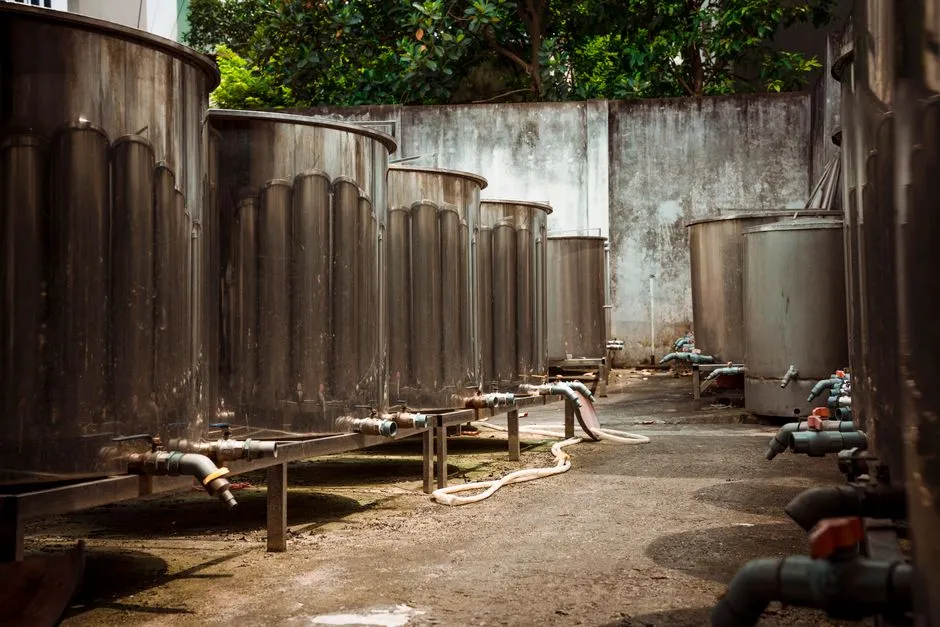
Capture in a flotation cell proceeds in three steps: collision, attachment, and rise. Micro-bubble flotation improves the first two and tolerates the third.
Collision probability rises sharply as bubble diameter falls. The particles that escape conventional DAF — sub-100 µm API crystals, sub-50 µm oil droplets, fine fermentation debris — sit in the size range where millimetre-scale bubbles have low encounter rates. Sub-50 µm bubbles dramatically expand that encounter rate, which is the principal reason micro-bubble flotation outperforms conventional DAF on fine pharmaceutical particulates.
Attachment is supported by the negative ζ-potential that has been reported on micro-bubbles in aqueous solution (cited within S2's references, building on Takahashi's work on micro-bubble formation, reaction, and destruction). A negatively charged micro-bubble adheres more readily to similarly charged hydrophobic particles when a coagulant or flocculant is dosed to compress the double layer. Without coagulant, attachment is weaker; with it, capture becomes efficient enough to justify the saturator pressure the micro-bubble generator requires.
Rise velocity decreases with bubble size, but a micro-bubble generator compensates by delivering far more bubbles per unit gas volume. S2 reports ~67% of bubbles below 20 µm under 0.9 MPa, an order-of-magnitude increase in bubble count over a millimetre-bubble DAF for the same air flow. Where API fines drop below 10–20 µm, pico-nano bubbles (mean sizes 150–240 nm reported in coal flotation, WVU 2014, S5) act as a secondary collector, bridging fine particles to larger carrier bubbles and reducing detachment probability.
Sizing a Micro Bubble / DAF Unit for Pharmaceutical Duty
There is no single vendor-agnostic sizing standard for micro-bubble flotation on pharmaceutical duty, because influent oil, suspended solids, API speciation, and solvent fraction vary widely between formulation, API, fermentation, and contract-manufacturing sites. The table below sets out the parameters a vendor meeting should cover, the cited evidence behind each value, and the inputs the buyer must still confirm on site. Where the cited evidence comes from a non-pharma matrix, the table calls that out so the engineer does not over-extrapolate.
| Parameter | Reported value or range | Source | Site-specific input to confirm |
|---|---|---|---|
| Bubble diameter distribution | ~67% of bubbles < 20 µm under 0.9 MPa on a TCRI-A generator | S2 (Sep. Purif. Technol., 2010, dyeing wastewater) | Bubble size distribution from a lab test on the actual plant effluent, not a generic reference |
| Saturation pressure | 0.9 MPa cited for micro-bubble generation; 0.4–0.7 MPa typical for conventional DAF | S2 for 0.9 MPa; conventional DAF range from general DAF engineering practice, not in research data | Compressor capacity, nitrogen/oxygen demand, and whether pharmaceutical-grade air is required |
| Recycle ratio | 20–50% is typical in conventional DAF; rises with influent oil/SS load | General DAF engineering practice, not in supplied research | Jar-test result on the actual stream; saturation-tank sizing must match chosen recycle |
| Hydraulic retention time in the flotation cell | 38 minutes optimum in oily-water RSM; 1 hour in 75 L pilot | S1 (UNBC 2024, oily wastewater) | Peak vs average hydraulic load; equalization upstream |
| Air-to-solid ratio | Not given in supplied research; depends on bubble size and SS load | No supporting evidence in research data | Calculate from TSS and chosen recycle ratio; request vendor-specific A/S curve |
| Reactor H/D ratio | 10, 20, 30 tested; performance only slightly affected, with gradual improvement at higher H/D | S1 (UNBC 2024) | Available headroom in existing equalization basin for retrofit |
| Coagulant type and dose | PAC, PFS, Al₂(SO₄)₃ tested at 70–110 mg/L (as Al or Fe) | S2 (Sep. Purif. Technol., 2010) | Optimum coagulant for the actual pharma matrix; downstream sludge-handling compatibility |
| Coagulant integration | Coagulation + micro-bubble flotation reduced required coagulant dose vs coagulation + conventional air-bubble flotation | S2 | Confirm dose reduction on pharma stream; verify effect on API removal |
| Flotation time and gravity pre-settling time | Both materially affected oil-separation efficiency in oily water | S1 | RSM or jar test on the plant's own wastewater |
Inputs the buyer must still confirm on site via jar tests, because the research data does not provide them for pharmaceutical matrices, include: influent oil and SS concentration, API speciation (the cited dyeing and oily-spill matrices do not carry APIs), solvent fraction, target COD/TSS removal, peak versus average hydraulic load, and downstream biological or MBR compatibility. HydropureWater automatic chemical dosing integrates with the saturator and should be specified together with the cell to keep coagulant dose on setpoint across batch swings.
Placing Micro Bubble Flotation in a Pharmaceutical Effluent Train
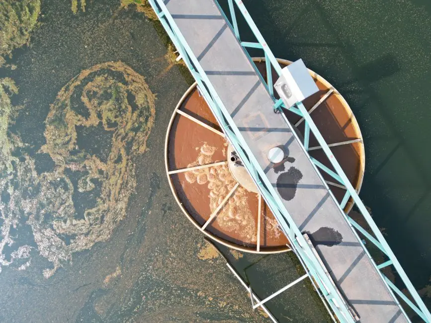
Micro-bubble flotation is not a stand-alone polish. It sits between upstream screening/equalization and downstream biological or membrane treatment, and the train configuration depends on whether the plant targets discharge compliance or high-purity reuse.
Train A — primary clarification: screening → equalization → micro-bubble/DAF → biological treatment (activated sludge or MBR) → disinfection or RO reuse. The directly relevant benchmarks are S2's COD/color/oil removals and the B/C uplift from 0.290 to 0.363 — that is the lift the biological stage inherits. The MBR is the cleaner of the two options because DAF + MBR is a documented combination for pharmaceutical residue streams (PubMed, S4).
Train B — pre-treatment for advanced polishing: micro-bubble/DAF → MBR → ozone or adsorption. S4 documents DAF-MBR followed by ozone for pharmaceutical residue streams, and S1 reports that combining NB/MB flotation with adsorption reached nearly 100% oil/water separation efficiency in oily-water tests. Either path requires the float sludge to be dewatered; a HydropureWater plate-and-frame filter press sized to the expected float yield keeps the upstream cell from being choked by accumulated scum, and it should be specified at the same time as the flotation cell. A HydropureWater MBR system is the membrane option that pairs with either train.
For scale-up, S1's 75 L pilot reaching 92% oil separation in one hour is the most defensible benchmark for the engineering scale-up factor between lab and full plant. The pilot is oily-water, not pharmaceutical, so the engineer should still run a site jar test before committing to a full-scale vessel.
Micro Bubble Flotation vs Conventional DAF: When the Premium Is Justified
The question for procurement is whether the higher saturator pressure, finer generator, and tighter controls of a micro-bubble unit earn their capex over a standard DAF on a given pharmaceutical matrix. The comparison below uses only the supplied research; conventional-DAF ranges that the research does not provide are marked accordingly.
| Criterion | Micro-bubble flotation | Conventional DAF | Source |
|---|---|---|---|
| Bubble size | ~67% of bubbles < 20 µm at 0.9 MPa (TCRI-A generator) | Millimetre-scale bubbles (size not specified in supplied research) | S2 (Sep. Purif. Technol., 2010) |
| KLa (oxygen mass-transfer coefficient) | 1.1754 min⁻¹ | 0.7535 min⁻¹ | S2 |
| COD removal uplift vs conventional air-bubble flotation in same reactor | +30% | Baseline | S2 |
| Color removal uplift | +110% | Baseline | S2 |
| Oil removal uplift | +40% | Baseline | S2 |
| Biodegradability (B/C) after treatment | 0.363 (from 0.290) | 0.301 (from 0.290) | S2 |
| Chemical dosing | Reduced coagulant dose reported vs coagulation + conventional air-bubble flotation | Baseline dose | S2 |
| Pilot oil removal on oily water | 92% in 1 hour (75 L pilot) | Gravity settling 4.62% in 1 hour (not strictly a DAF comparison, but a benchmark) | S1 (UNBC 2024) |
| Chemical-free operation | Reported as chemical-free in oily-water tests (no coagulant dosed) | Typically paired with coagulation | S1 |
| Saturation pressure | 0.9 MPa cited for micro-bubble generation | 0.4–0.7 MPa typical in DAF practice (not in supplied research) | S2 for micro-bubble; DAF range from general practice |
Micro-bubble flotation earns its premium when the influent carries high emulsified oil or suspended solids, fine API particulates below the millimetre-bubble DAF capture range, variable batch composition, or strict downstream biological limits that benefit from the higher B/C ratio reported in S2. Conventional DAF remains adequate for relatively coarse, low-API oily streams and for plants with constrained capex — the cited evidence does not support specifying micro bubbles where the matrix is benign. Either way, S1 found that flotation time, gravity pre-settling time, and initial oil concentration all materially affected performance, so the final sizing must come from on-site jar tests, not from the literature alone.
Frequently Asked Questions
What does micro bubble flotation actually do that a standard DAF does not?
It generates bubbles in the tens of micrometres rather than millimetres, which raises the oxygen mass-transfer coefficient KLa from 0.7535 to 1.1754 min⁻¹ in the same reactor (Sep. Purif. Technol., 2010, S2). The smaller bubble size raises collision probability on sub-100 µm particles, which is why micro-bubble flotation lifts fine API crystals, emulsified oil droplets, and fermentation cell debris that conventional DAF lets through. It also raises the B/C ratio at the outlet, which lowers the load on the downstream biological or MBR stage.
How is a micro-bubble or DAF unit sized for a pharmaceutical plant, and what inputs must the buyer provide?
Sizing requires the influent oil and suspended-solids concentration, API speciation, solvent fraction, peak and average hydraulic load, target COD/TSS removal, and downstream biological or MBR compatibility — none of which the supplied research provides for a pharmaceutical matrix. The 2010 dyeing-wastewater study (S2) gives the bubble generator operating point (0.9 MPa, ~67% of bubbles under 20 µm) and the coagulant window (PAC, PFS, Al₂(SO₄)₃ at 70–110 mg/L as Al or Fe), and the UNBC 2024 oily-water work (S1) gives hydraulic-retention guidance (38 minutes optimum at lab scale, 1 hour in a 75 L pilot). The buyer should request a jar test on the plant's own wastewater before committing to vessel volume, recycle ratio, and air-to-solid ratio.
Where should the micro-bubble unit sit in a pharmaceutical effluent train?
It should sit after screening and equalization and before biological treatment or an MBR. The two common trains are (A) screening → equalization → micro-bubble/DAF → biological or MBR → disinfection or RO, and (B) micro-bubble/DAF → MBR → ozone or adsorption polishing. The second is the documented DAF-MBR + ozone path for pharmaceutical residue streams (PubMed, S4), and pairing micro-bubble flotation with downstream adsorption has been shown to approach 100% oil removal in oily-water pilots (S1). Float sludge from the cell should be dewatered on a plate-and-frame or screw press, sized at the same time as the flotation cell.
How should a pharma engineer select a micro-bubble flotation supplier, and what compliance or delivery risk should they price in?
Selection should turn on three evidence-backed checks rather than capex alone. First, the supplier must demonstrate a bubble-size distribution on the actual plant effluent — not a generic reference — because the cited 67%-under-20-µm result (S2) was measured on dyeing wastewater and may not transfer to a pharmaceutical matrix. Second, the supplier must provide pilot or full-plant oil and COD removal data on a stream compositionally similar to the buyer's, since the supplied research is from oily-spill and dyeing matrices, not API effluent. Third, the supplier must confirm the saturator pressure the generator actually requires against the plant's compressed-air capacity, because micro-bubble generation in the cited work runs at 0.9 MPa (S2), well above the 0.4–0.7 MPa range of conventional DAF, and a retrofit that cannot deliver that pressure will not achieve the cited KLa. Delivery lead time should be priced against the saturator-vessel fabrication schedule, which typically gates the whole skid.