
Which Federal Rule Applies to a Calhoun County Fabricated Metals Plant
40 CFR Part 433 (Metal Finishing) covers forming, finishing, forging, foundry, metal spraying, and machining-wash operations that are co-located with plating or anodizing lines. A stamping shop that ships only dry parts to a separate finisher is generally outside the category; a facility that runs its own zinc, nickel, or chromic acid tank is inside it. The rule splits limits into PSES for existing sources and PSNS for new sources, with PSNS tighter because it applies to sources constructed after promulgation. Local POTW limits developed under 40 CFR 403.5 are always at least as stringent as the categorical standard and typically add copper, nickel, zinc, lead, and silver caps plus oil and grease, TSS, and pH. Because most POTW pretreatment programs enforce PSNS-equivalent local limits on all industrial users as a conservative baseline, an existing plant should still design to PSNS numbers even when only PSES formally applies.
Engineers in Calhoun County should walk the floor and answer two questions before any equipment is specified: (1) does the site run any wet process on a metal surface that is part of an effluent-bearing operation covered by Part 433, and (2) what does the local POTW table add on top of the federal table? If the answer to (1) is yes, the plant designs to whichever limit is stricter on each parameter, and that envelope is built from the POTW table, not from the federal table alone.
| Parameter | 40 CFR Part 433 basis | Local POTW basis (40 CFR 403.5) |
|---|---|---|
| Cd, Cr, Cu, Pb, Ni, Ag, Zn | Categorical PSES and PSNS daily-max and monthly-average limits | Local limits always at least as stringent; commonly add caps not in 433 |
| Oil and grease | Not always in 433 numeric table | Frequently added by POTW as a local cap |
| Total suspended solids | Not always in 433 numeric table | Frequently added by POTW as a local cap |
| pH | Process-side range; 433 reports numeric limits by pollutant | Discharge-side range, typically 6–9 |
| Total toxic organics | Listed in 433 | Adopted by reference through local limits |
The Four Contaminant Families That Drive Pretreatment Design
Every fabricated metals floor generates the same four contaminant families regardless of process mix, and the treatment train is built around them. Family 1 is free and emulsified oils from stamping, machining, and drawing compounds, separated physically or broken chemically upstream of any precipitation stage. Family 2 is dissolved heavy metals (Zn, Ni, Cu, Cr, Pb, Cd) from plating rinsewater and acid pickling, which require pH-driven hydroxide precipitation. Family 3 is hexavalent chromium from chromic acid anodizing, hard chrome, and conversion coating, plus cyanide wherever alkaline cyanide plating is still in use. Family 4 is total suspended solids from grinding swarf, casting sand, and hydroxide floc carryover, removed after precipitation by DAF or lamella clarification.
Two sequence rules are non-negotiable. First, cyanide must be destroyed before metals precipitation, or it will resolubilize the precipitates downstream, causing effluent to fail across multiple metals. Second, oils must come off before any precipitation chemistry, because oils strip reagents and blind DAF nozzles. Treating the four families in the wrong order is the most common cause of simultaneous failures on a compliance sample.
Per HydropureWater field data from 2026, a mixed floor drain entering pretreatment typically runs oils at 50–500 mg/L, total dissolved metals at 5–200 mg/L, TSS at 100–1,000 mg/L, and pH swinging between 2 and 12 across batch dumps. A hard chrome line will spike Cr(VI) above 50 mg/L and drop pH below 2 on a rinse dump. These are the numbers a week of composite sampling must capture before any equalization basin is sized.
| Family | Source on a fabricated metals floor | Required unit operation | Skipped-step failure mode |
|---|---|---|---|
| 1 — Oils (free + emulsified) | Stamping, machining, drawing compounds | API interceptor, skimmer, or emulsion break tank upstream of chemistry | Reagent stripping, DAF nozzle blinding, TSS carryover |
| 2 — Dissolved metals (Zn, Ni, Cu, Cr, Pb, Cd) | Plating rinsewater, acid pickling | Hydroxide precipitation at pH 8.5–9.5 | Metal limits fail, sludge quality poor |
| 3 — Cr(VI) and cyanide | Chromic acid anodizing, hard chrome, alkaline cyanide plating | Cr(VI) reduction at pH 2–3, ORP ~250–300 mV; alkaline chlorination of CN⁻ | Cr(VI) fails, CN⁻ resolubilizes precipitates |
| 4 — TSS | Grinding swarf, casting sand, hydroxide floc | DAF or lamella clarification post-precipitation | TSS cap fails, hauled sludge volume rises |
The 2026 Treatment Train: Stage by Stage
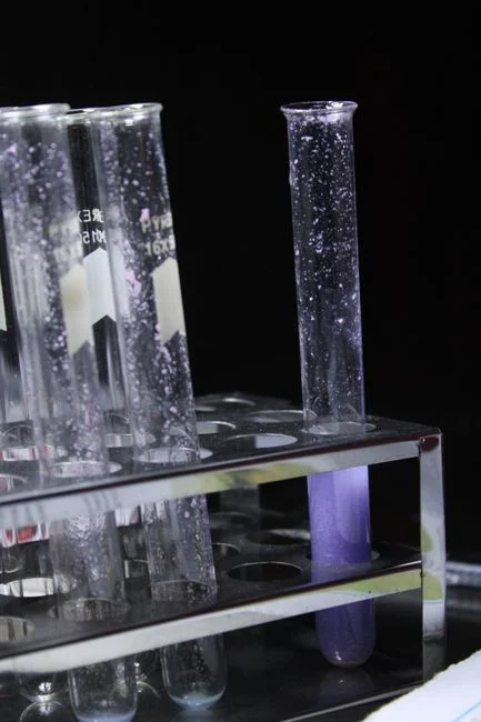
The standard sequence a fabricated metals plant uses to hit PSNS-equivalent POTW limits is equalization, oil and grease removal, hexavalent chrome reduction, cyanide oxidation, hydroxide precipitation, dissolved air flotation or lamella clarification, and pH trim. Each step has a defined inlet spec, outlet spec, and a failure mode if it is skipped.
Step 1 — Flow equalization. Target outlet is pH 6–9 smoothed and flow CV below 0.5. Plating shops run batch dumps, not steady flow, so equalization is the unit operation that makes downstream chemistry work. The sampling prerequisite is non-negotiable: a full week of composite flow must be taken before equipment is specified, because a 4-hour composite that misses a Friday afternoon dump will undersize the equalization basin.
Step 2 — Oil and grease removal. Use an API interceptor, skimmer, or emulsion-breaking tank upstream of any precipitation stage. Oils strip reagents and blind DAF nozzles if they reach the chemistry stage. A DAF system for the metals precipitation step downstream depends on this step being effective.
Step 3 — Hexavalent chrome reduction. Sodium metabisulfite (or ferrous sulfate) at pH 2–3 with ORP controlled around 250–300 mV reduces Cr(VI) to Cr(III), which then precipitates as Cr(OH)3 in the pH 8.5–9.5 stage. Cr(VI) hydroxide is soluble at any plausible treatment pH, so skipping reduction means Cr(VI) passes through to discharge.
Step 4 — Cyanide oxidation. Use NaOCl alkaline chlorination before metals precipitation. The ORP setpoint and pH window must be validated against the specific bath chemistry, because free cyanide and metal-cyanide complexes respond differently.
Step 5 — Hydroxide precipitation. Dissolved metals are precipitated at pH 8.5–9.5 with pH and ORP feedback control on the dosing skid. A lamella clarifier alternative for high-solids flows can replace the DAF for streams with very high TSS and minimal floatable oil.
Step 6 — Dissolved air flotation or lamella clarification. This step removes floc and TSS.
Step 7 — pH trim. Final pH adjustment to the POTW band, typically 6–9, is the last active step before the compliance sample point. Skipping any single step results in at least one parameter failing on the compliance sample, and in practice, three parameters usually fail together.
DAF Sizing: The Three Knobs That Decide Pass or Fail
DAF performance is governed by three knobs: hydraulic surface loading, air-to-solids ratio, and recycle rate. Knob 1 is hydraulic surface loading, 4–20 m/h depending on model and floc density, with higher values for floated floc and lower values for dense floc. Pushing it too high lets floc escape with the overflow. Knob 2 is air-to-solids ratio, 0.005–0.060 with 0.02 a typical design point; higher A/S gives a drier float but costs blower power and can shatter fragile floc. Knob 3 is recycle rate, 10–30% of forward flow, with higher recycle improving TSS removal but diluting chemistry and inflating equalization demand.
A rotary mechanical bar screen upstream of equalization keeps rags, wipes, and tramp metal out of the sludge train and is the single most common cause of premature press-cloth failure when it is missing. The DAF system for the metals precipitation step must be specified with all three knobs called out on the same drawing as the recycle pump and saturator.
| Knob | Operating range | Design point | Push it higher and… | Push it lower and… |
|---|---|---|---|---|
| Hydraulic surface loading | 4–20 m/h | Mid-range, set by floc density | Floc escapes with overflow | Unit is oversized for the flow |
| Air-to-solids ratio (A/S) | 0.005–0.060 | ~0.02 | Drier float, more blower power, fragile floc can shatter | Wet float, lower TSS removal |
| Recycle rate | 10–30% of forward flow | 15–20% | Better TSS removal, diluted chemistry, larger EQ demand | Lower TSS removal, sharper chemistry |
Chemical Dosing, Controls, and Sludge Handling
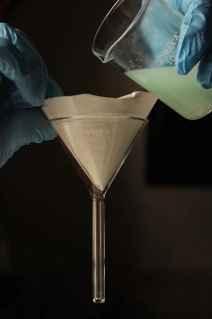
Chemical dosing is governed by feedforward (flow-paced) and feedback (pH/ORP) control on a skid-mounted PLC chemical dosing system. The four chemicals are NaOH or H2SO4 for pH trim, sodium metabisulfite for chrome reduction, NaOCl for cyanide destruction, and anionic or cationic polymer for floc. Skid-mounting cuts field install time, forces the integrator to bench-test interlocks before shipment, and gives the operator one panel to lock out instead of five loose pumps. Each pump needs a calibration column and a stroke-count totalizer; without those, the operator is dosing blind.
Floated metal-hydroxide sludge runs 2–5% dry solids out of the DAF and dewaters to 25–35% with a plate and frame filter press for metal hydroxide sludge. A belt press is cheaper and continuous but caps out around 22% dry solids on metal hydroxide, so if the hauler is paying by wet ton, plate and frame pays back. Alarm and shutdown interlocks on pH excursion, ORP out of range, and high TSS should automatically divert flow back to the equalization basin header so a chemistry upset does not become a discharge violation.
When Polishing Is Required and the 2026 PFAS Question
Most fabricated metals plants hit sewer limits with the train above and never need a polishing step. The cases that do are predictable: the POTW tightens local limits below PSNS, the plant wants to reuse rinsewater and needs RO-quality feed, or a new rule forces a polish stage.
For BOD and COD tightening or water reuse, a submerged PVDF MBR system delivers sub-1 μm filtration and stable effluent suitable for cooling tower makeup or rinsewater reclaim. For sub-ppm TDS or specific metal caps such as nickel below 0.1 mg/L for some reuse specs, an RO system is required, and the multi-media filter upstream must hold SDI15 below 3 or the RO membranes fail early. EPA has a PFAS rulemaking scoped to chrome finishing facilities in 2026 with no current numerical limit, per the EPA Metal Finishing Effluent Guidelines page; the correct design move is to leave room for anion exchange or GAC as a future bolt-on rather than pay to operate it ahead of any actual limit. Closed-loop zero liquid discharge is rarely economic for a fabricated metals plant unless water scarcity or a specific reuse-economics case supports the capital.
Frequently Asked Questions
Does 40 CFR
Frequently Asked Questions
Does 40 CFR Part 433 apply to a stamping-only fabricated metals plant in Calhoun County?
40 CFR Part 433 (Metal Finishing Point Source Category) applies only if the facility performs at least one of the six core operations: electroplating, electroless plating, anodizing, coating, chemical etching and milling, or printed circuit board manufacturing. A stamping-only facility that does not perform these specific processes is typically exempt from Part 433 and instead falls under local Calhoun County POTW categorical limits or 40 CFR Part 403 General Pretreatment Regulations.
PSES vs PSNS — which set governs an existing fabricated metals plant that is being modified in 2026?
Pretreatment Standards for Existing Sources (PSES) continue to govern the facility if the modifications do not meet the regulatory definition of a "new source." A new source is defined under 40 CFR 403.3 as a facility where construction commenced after the publication of proposed categorical standards, or if the facility undergoes a major process replacement that constitutes a "new source" determination by the permitting authority.
What indicative CAPEX and lead time should we expect for a 5–20 m³/h DAF-based fabricated metals pretreatment skid in 2026?
For a 2026 installation, a skid-mounted Dissolved Air Flotation (DAF) system capable of 5–20 m³/h typically ranges from $180,000 to $450,000 depending on the degree of automation, materials of construction, and integrated chemical dosing skids. Procurement lead times currently average 24 to 36 weeks from the date of final engineering approval to site delivery.
What is the most common cause of pretreatment failure for fabricated metals plants, and how do we prevent it?
The most frequent cause of pretreatment failure is the inconsistent management of emulsion-breaking chemistry, often resulting in high oil and grease (O&G) carryover that exceeds local limits. This is prevented by implementing automated real-time pH and ORP monitoring, alongside regular jar testing to adjust polymer and coagulant dosages in response to shifting influent concentrations from production cycles.
Is a PFAS polishing stage required for chrome finishing in 2026, and when should it be installed?
While federal standards for PFAS in industrial discharge are rapidly evolving under EPA’s Strategic Roadmap, chrome finishing plants should anticipate mandatory PFAS polishing stages by 2026–2027 to comply with upcoming pretreatment permit renewals. Installation should be prioritized during the design phase of any current facility upgrades to integrate ion exchange or granular activated carbon vessels before the final effluent discharge point.