What FGD in a Power Plant Actually Does
FGD (flue gas desulfurization) in a coal-fired power plant is an air-pollution control step installed downstream of the boiler and particulate control, distinct from SCR/DeNOx, which targets NOx. In a wet limestone or wet lime system, SO2 is absorbed into a limestone or lime slurry inside a spray tower, producing calcium sulfite that is oxidized to gypsum (CaSO4·2H2O). The wet FGD absorber also captures a fraction of entrained particulate, which is why an integrated single-tower design that combines SO2 removal with particulate collection is common, as implemented in the HydropureWater FGD scrubber. Compliance anchors that drive the design include the U.S. EPA NSPS for SO2, the EU Industrial Emissions Directive 2010/75/EU, and the World Bank/IFC EHS Guidelines for Thermal Power Plants.
Because the absorber sprays a reactive slurry continuously, the unit is a water-intensive loop: it consumes make-up water for the slurry, produces a dewatered gypsum byproduct, and bleeds a contaminated wastewater stream that requires treatment before discharge or reuse.
Inside the Wet FGD Loop: Hydrocyclones, Gypsum, and Blowdown
Absorber sump slurry is sent to a primary hydrocyclone train to separate gypsum solids from the liquid phase. The underflow is the gypsum product; the overflow partially recycles to the absorber and partially bleeds off as the FGD wastewater stream. Gypsum typically undergoes further dewatering—additional hydrocyclone stages, vacuum filtration, or a centrifuge—before being stockpiled or sent off-site, with a small filtrate stream rejoining the wastewater bleed.
Measured separation efficiencies from a thermal-plant study (Bilen, 2021) clarify the asymmetry of this split. The study used D25 inlet sizing and Malvern Mastersizer particle-size distribution (PSD) analysis to quantify the cut. In an operating unit, the gypsum hydrocyclone achieved 77.5% separation efficiency, while the wastewater hydrocyclone achieved only 4.0%. The engineering consequence is that the wastewater hydrocyclone is intentionally a coarse cut: it allows fines, dissolved species, and most of the soluble load to pass to the blowdown stream rather than back to the absorber.
| Hydrocyclone | Service | Measured separation efficiency (Bilen, 2021) | Method |
|---|---|---|---|
| Gypsum hydrocyclone | Gypsum classification / dewatering | 77.5% | D25 inlet sizing, Malvern Mastersizer PSD |
| Wastewater hydrocyclone | FGD blowdown clarification | 4.0% | D25 inlet sizing, Malvern Mastersizer PSD |
The 4.0% figure explains why the blowdown stream is concentrated: the unit process that creates the wastewater is, by design, passing soluble species through.
What Is in FGD Wastewater — and Why It Is Hard to Treat
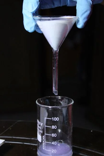
FGD wastewater contains specific chemical constituents including chemical oxygen demand (COD), ammonia, nitrate, nitrite, dithionate (a by-product of hydrogen sulfite oxidation), selenium, and boron, all carried in a high-TDS matrix of chloride and sulfate from the limestone and coal. Selenium often challenges generic treatment schemes. Selenite (Se4+) is removable by standard coagulation and sedimentation, but selenate (Se6+) is not, requiring biological reduction or a composite-metal polishing step. COD is also split: most of it is organic and amenable to biological treatment or activated-carbon adsorption, but a "hard-to-degrade" fraction comes directly from the wet FGD chemistry and requires a tailored polishing step.
High-TDS FGD matrices cause polyatomic interferences during ICP-MS analysis of trace elements, biasing arsenic and selenium detection at low-ppb concentrations. Consequently, the EPA developed FGD-specific standard operating procedures used alongside EPA Method 200.8 under the flexibility provisions of 40 CFR 136.6 (U.S. EPA, 2024).
| Constituent | Source in WFGD | Treatment difficulty |
|---|---|---|
| COD (organic) | Coal, limestone, process water | Biological or activated carbon |
| COD (hard-to-degrade) | Wet FGD chemistry | Tailored polishing step required |
| Ammonia / nitrate / nitrite | NOx absorption, NS-compounds | Fixed-bed biological nitrification |
| Dithionate | Oxidation of hydrogen sulfite | Difficult; targeted removal step |
| Selenite (Se4+) | Coal combustion | Coagulation / sedimentation |
| Selenate (Se6+) | Coal combustion | Biological or composite-metal reduction |
| Boron | Coal, limestone | Separate polishing step |
A standard biological WWTP designed for sanitary or light-industrial load will under-perform on FGD blowdown, necessitating a dedicated FGD WWTP or a polishing side-stream ahead of the main plant outfall.
Lime vs Limestone and the Choice of Reagent
Limestone (CaCO3) slurry is the default wet FGD reagent, offering lower costs, a milder wastewater profile, and higher slurry volume. Lime (CaO/Ca(OH)2) provides higher SO2 removal efficiency at smaller equipment scale, but increases sludge volume and reagent operating cost while pushing the absorber effluent toward higher pH and higher calcium load.
For a buyer, the trade-off involves balancing reagent cost and availability against absorber footprint and wastewater load. Because the reagent choice is set during front-end engineering and is not easily reversed, it belongs in the early specification package. The HydropureWater FGD scrubber is designed to operate in either lime or limestone wet-scrubbing mode as a single-tower configuration, ensuring the reagent decision is addressed at the equipment-spec stage.
Treatment Train Options for FGD Blowdown
A conventional FGD wastewater train consists of equalization, pH adjustment, coagulation and sedimentation for Se4+ and suspended solids, fixed-bed biological nitrification for ammonia, biological Se6+ reduction or composite-metal polishing, and a final clarification or solids-separation step. Mitsubishi Power recommends fixed-bed biological treatment over floating-bed systems for ammonia because fixed-bed media retain nitrifiers across low-N influent swings without requiring external nitrogen dosing.
For the final solids-separation step, a DAF system for FGD blowdown is suitable when the stream carries oils, fine colloids, or biological floc that a gravity clarifier struggles to capture. A lamella clarifier fits higher-flow, lower-solids duties where footprint and hydraulic loading are primary concerns. Chemical conditioning across the train is handled by a PLC-controlled chemical dosing skid. Boron removal, where required, is a separate polishing step.
For finer bubble-mass-transfer work in the DAF step, the micro-bubble flotation design criteria guide details sizing inputs, and the filter beds in water treatment guide covers downstream polishing media selection.
2026 Compliance Lens for Coal-Fired FGD Operators
The Steam Electric Power Generating Effluent Guidelines at 40 CFR 423, updated through the 2020, 2024, and 2025 rulemakings, set chemical-specific limits and a zero-liquid-discharge (ZLD) trajectory for FGD blowdown in the United States. In the European Union, IED 2010/75/EU BAT-AELs for coal-fired plants set ceilings on SO2, dust, and water discharge that the FGD scrubber design must meet. The World Bank/IFC EHS Guidelines for Thermal Power Plants serve as the benchmark for non-OECD projects and frequently drive project-financing approval.
Any plant reporting trace metals (As, Se, Hg) should use the FGD-specific ICP-MS SOPs developed by the EPA to address matrix interferences, as standard methods under-report at low-ppb levels (U.S. EPA, 2024). Achieving compliance in 2026 requires integrating air-side limits, water-side limits, and analytical methods into the procurement conversation.
What to Send a Supplier Before You Ask for a Quote
Providing a complete input package ensures a more accurate FGD and wastewater-train quotation. At minimum, a buyer should provide coal analysis (Cl, S, Hg, Se) and limestone purity; boiler flue gas flow, SO2 inlet, target outlet, and dust load; FGD blowdown flow and 24-hour composite chemistry (TDS, TSS, NH3-N, Se4+/Se6+, B, and COD fractions); the discharge route (surface water, sewer, ZLD, or cooling-water co-treatment); and the local compliance anchor (US ELG, EU IED BAT-AEL, or World Bank/IFC EHS). Without these details, vendor proposals may fail to meet technical requirements.
Frequently Asked Questions
What drives the cost of an FGD wastewater treatment system?
Reagent consumption (lime versus limestone), blowdown flow, and the target discharge route (surface water, sewer, or ZLD) are the primary cost drivers, as they determine the size of the equalization, biological, and polishing unit operations. For project-specific pricing, request a quotation tied to your 24-hour composite blowdown chemistry and discharge-route option.
How do I choose between a DAF and a lamella clarifier for FGD blowdown?
Specify a DAF when the stream carries oils, fine colloids, or biological floc that require bubble attachment for separation; specify a lamella clarifier when the duty involves higher flow, lower solids, and constrained space. Request hydraulic-loading and solids-loading data from the vendor based on your influent TSS and oil/grease content.
Why does FGD wastewater need its own treatment train instead of going to the main plant WWTP?
High TDS, dithionate, ammonia, Se6+, and boron load a generic biological WWTP outside its design envelope, and most FGD matrices cause ICP-MS interferences that bias low-ppb trace-metal reporting (U.S. EPA, 2024). A dedicated train or a polishing side-stream ensures each unit process operates within its design range and maintains regulatory compliance.
Which compliance standard should I specify for a 2026 FGD project?
For a U.S. site, the controlling rule is 40 CFR 423 (Steam Electric Effluent Guidelines) and its 2024/2025 revisions; for an EU site, IED 2010/75/EU BAT-AELs; for a project-financed non-OECD site, the World Bank/IFC EHS Guidelines for Thermal Power Plants. Confirm the version with the local regulator before locking the design basis, and require the FGD-specific ICP-MS SOPs for any trace-metal compliance sample.