
Why Biodiesel Wastewater Behaves Differently in a DAF
Biodiesel wash-water is not a generic industrial DAF feed. The combination of free glycerol, residual methanol, sodium or potassium soap generated when homogeneous base catalysts (NaOH, KOH, NaOMe) neutralize free fatty acids, and emulsified FOG produces a colloidal matrix that resists the bubble-particle attachment a DAF unit relies on. A DAF sized as if it were treating refinery desalter or food-processing FOG will underperform because the float layer is a glycerol–soap–oil composite, not a simple oil blanket, and the soluble COD from glycerol and methanol passes through the unit largely untouched. That is why Desalination (2011) explicitly documents acidification combined with coagulation as a DAF-efficiency-enhancing step for biodiesel wastewater rather than a generic pretreatment.
Henry's law sets the physics underneath every DAF design. Air forced into the recycle stream under pressure reaches an equilibrium concentration described by Henry's law; ScienceDirect (DAF overview) notes that about 24 ppm of air dissolves in water at 1 atm (14.7 psia), and that this concentration scales with absolute pressure. At roughly 6 atm (~90 psig) the predicted concentration is about 6 × 23 ≈ 130 ppm. Because dissolution in the pressurized holding tank is not 100% efficient, a saturation correction factor f = 0.5–0.8 is applied to convert theoretical solubility into the air actually carried by the recycle. Bubbles nucleate at the tank bottom when the recycle is depressurized, attach to floc particles driven by hydrophobic interaction, and lift them once the bubble–particle aggregate has a specific gravity below 1.0. Getting that attachment to happen on a biodiesel feed is the entire design problem.
The Three DAF Configurations and Why Recycle Pressurization Wins for Biodiesel
Three DAF topologies appear in vendor literature, and only one of them is appropriate for floc-bearing industrial wastewater. Recycle pressurization saturates a clarified side-stream in an external air drum and re-injects it through a pressure-reduction valve at the flotation-tank inlet; this is the dominant industrial configuration and the one to specify for biodiesel. Direct pressurization puts the full forward flow through the pressurization pump and valve, and ScienceDirect notes that the resulting shear destroys chemical flocs, which is why it is not widely used for industrial wastewater. Induced gas flotation (IGF) and froth flotation are related processes; Wikipedia notes that IGF is the typical oil-industry alternative where explosion risk rules out compressed air, and that some oil-handling facilities use nitrogen rather than air for that reason.
Lamella or parallel-plate packs can be added inside either circular or rectangular DAF vessels to multiply effective separation area, at the cost of more sludge to scrape. The choice between circular and rectangular is independent of the pressurization topology and is covered later. For biodiesel effluent, the spec should call out recycle pressurization with a pressure-rated saturator tank, a recycle pump sized to deliver the calculated recycle flow, an air compressor sized for the calculated air mass, and a pressure-reduction valve at the flotation-cell inlet. A HydropureWater DAF system ships with that topology as standard.
| Configuration | Pressurized stream | Biodiesel effluent fit | Key drawback |
|---|---|---|---|
| Recycle pressurization | Clarified side-stream | Preferred — floc intact | Saturator tank and recycle pump required |
| Direct pressurization | Full forward flow | Not recommended | Pump/valve shear destroys floc (ScienceDirect) |
| Induced gas flotation (IGF) | Mechanical induction | Used where explosion risk rules out air | Larger bubbles, lower separation efficiency |
Coagulation and Flocculation Chemistry for Biodiesel DAF

Three chemistry decisions determine whether the DAF removes anything: pH, coagulant, and polymer aid. The sequence is documented for biodiesel wastewater in Desalination (2011) and the general mechanism is summarized in the ScienceDirect DAF overview (Figure 7-104 description). The first step is acidification, which splits sodium soap into free fatty acids and drives the feed toward a pH window in which coagulants perform; the second is coagulant dosing, typically a metal salt that neutralizes colloidal charge and forms a hydroxide floc; the third is an anionic polymer injected at the flotation-cell inlet to build the larger floc that entrains micro-bubbles.
For soap-laden biodiesel feeds, ferric chloride is generally preferred over aluminum sulfate because it works across a wider pH window and forms denser floc that entrains bubbles more reliably (Wikipedia DAF; ScienceDirect topics). The actual dose, however, must come from a jar test on the real effluent, not from a textbook default, because biodiesel wastewater composition varies widely with feedstock. The jar-test output the engineer records is residual turbidity, residual FOG, and float-solids concentration across a matrix of coagulant dose, pH, and polymer dose. That matrix is the input to the A/S and saturator calculations in the next section, and it is also the input a vendor needs in order to size the chemical dosing skid.
Two inputs are non-negotiable before any of this chemistry work begins: a full influent characterization (COD, BOD, FOG, total glycerol, methanol, pH, temperature, TSS) and a documented jar-test protocol. Without both, the dosing system is being specified blind. The coagulant and polymer feed lines themselves are typically delivered as a PLC-controlled coagulant and polymer dosing skid with separate pumps, static mixers, and a flocculation tank ahead of the DAF inlet.
| Step | Chemical / action | Target | Source |
|---|---|---|---|
| 1. Acidification | Mineral acid to pH 3–5 | Split sodium soap to free fatty acids | Desalination (2011) |
| 2. Coagulant | Ferric chloride (preferred) or aluminum sulfate | Charge neutralization, hydroxide floc | Wikipedia DAF; ScienceDirect |
| 3. Polymer aid | Anionic polymer at DAF inlet | Build larger floc, entrap micro-bubbles | ScienceDirect (Figure 7-104) |
| 4. Jar test | Matrix of dose, pH, polymer | Output residual turbidity, FOG, float solids | Engineer-performed |
Sizing the DAF: A/S, Recycle Ratio and Saturator Pressure
The air-to-solids ratio (A/S) is defined as the mass of air supplied per day divided by the mass of solids removed per day, and ScienceDirect states that A/S values in the range 0.02–0.06 lb air per lb solids result in optimal flotation. Below that band there is not enough bubble surface to lift the floc; above it, unattached bubbles coalesce and stir the tank. The required air mass is therefore the design solids load multiplied by the chosen A/S, and that number sets the compressor and air-delivery size.
At the saturator, the dissolved-air concentration is set by Henry's law and the saturation efficiency. ScienceDirect states that at 1 atm roughly 24 ppm of air is dissolved in water, that at 6 atm (~90 psig) the prediction is about 130 ppm, and that an efficiency factor f = 0.5–0.8 is applied to the theoretical value to obtain the actual concentration carried by the recycle. Using f = 0.5 gives a conservative design; using f = 0.8 credits a well-designed saturator with full packing and adequate retention. The engineer should also know that operating pressures between 60 and 120 psig cover most applications (ScienceDirect, "Optimum Pressure" section) and that the trade-off is real: higher pressure shrinks the saturator tank and the recycle flow but increases pump and compressor power.
The recycle ratio is derived from the air balance, not chosen from a default. Required air mass (lb/day) divided by the dissolved-air concentration in the recycle (lb of air per lb of recycle water, obtained by converting the ppm figure at the chosen pressure and f) yields the required recycle flow. The work is the engineer's own — the answer depends on the chosen pressure and the chosen f, so the formula is what travels with the RFQ, not a recycled vendor number. The saturator pump horsepower is then cross-checked with HP = Q·ρ·H / (550·η) where H is the saturator pressure expressed in feet of water (ScienceDirect, equation 7-77).
| Parameter | Documented value | Source |
|---|---|---|
| Air-to-solids ratio (A/S) | 0.02–0.06 lb air / lb solids | ScienceDirect, "Air-to-Solids Ratio" |
| Dissolved air at 1 atm | ≈ 24 ppm | ScienceDirect, DAF overview |
| Dissolved air at ~6 atm (90 psig), theoretical | ≈ 130 ppm (6 × 23) | ScienceDirect, DAF overview |
| Saturation efficiency f | 0.5–0.8 | ScienceDirect, DAF overview |
| Operating pressure range | 60–120 psig | ScienceDirect, "Optimum Pressure" |
| Pump horsepower | HP = Q·ρ·H / (550·η), H in ft of water | ScienceDirect, equation 7-77 |
Selecting Tank Geometry and Hydraulic Residence Time
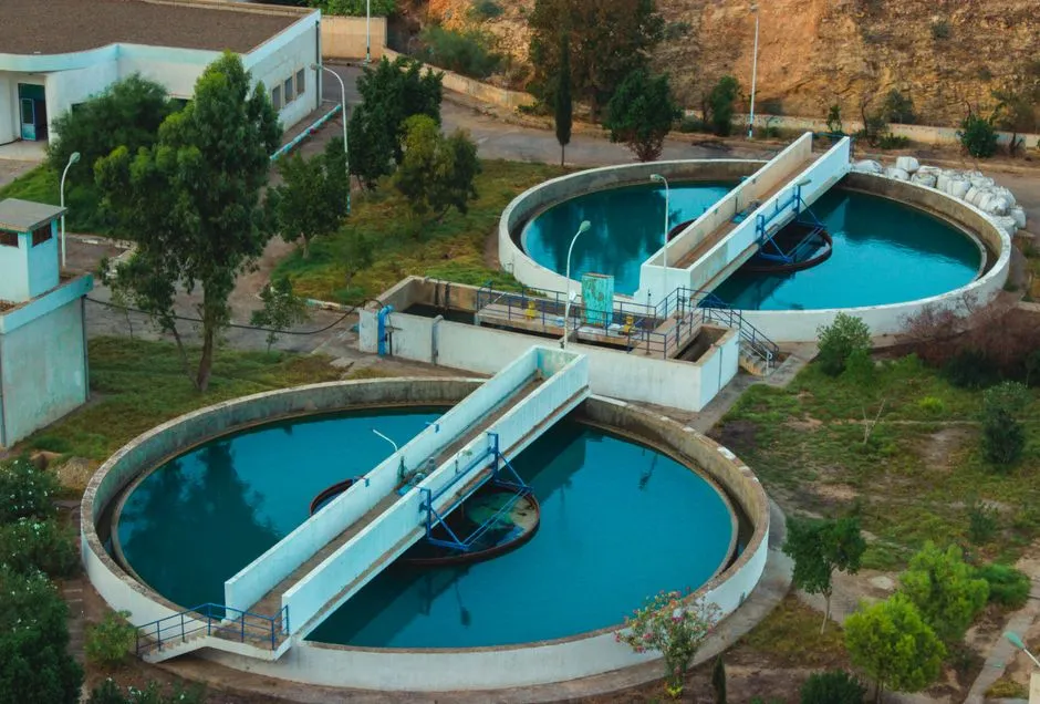
DAF vessels come in two geometries, and the choice is operational, not chemical. Circular DAF units deliver roughly 3 minutes of hydraulic residence time and use a spiral-scoop skimmer, which Wikipedia identifies as the higher-efficiency-per-unit-area option. Rectangular DAF units deliver 20–30 minutes of residence time, which gives the system hydraulic buffering against the slug loads typical of a batch transesterification plant that discharges its wash-water in pulses rather than a smooth 24-hour average. For most biodiesel facilities, rectangular is the safer default because the FOG and soap spikes from a single batch reactor can briefly exceed the steady-state design load.
Surface loading rate is the parameter that converts a chosen flow into a tank top area; tank area equals flow divided by the hydraulic loading rate, and the loading rate is a vendor-specific input the engineer must request. Lamella packs can be added inside either geometry to multiply effective separation area (Wikipedia DAF), at the cost of more sludge to remove and more packing to clean. The decision the engineer is making is layout-driven (footprint, skimmer access, hydraulic buffering) rather than chemistry-driven, and the DAF vendor should be asked to quote both geometries against the design flow before the geometry is locked.
Downstream Sludge Handling and What to Put on the RFQ
The float cake coming off a biodiesel DAF is a glycerol–soap–oil matrix with very little fiber content. Belt presses perform poorly on greasy, low-fiber cake because the water does not release readily, so the downstream dewatering step is usually a plate-and-frame filter press rather than a belt press. The float-cake mass is estimated from the removed solids plus the attached water, and the target dry-solids content after pressing is a vendor-specific input the engineer must request along with cycle time, cake thickness, and filtrate quality. A plate-and-frame filter press for the float-cake dewatering step is the typical pairing, and the same PLC-controlled coagulant and polymer dosing skid used for the DAF often feeds the press as well.
The DAF RFQ itself should be specific enough to force an apples-to-apples comparison. Items the engineer should include: design flow and peak flow; design TSS and FOG; design A/S within the 0.02–0.06 band; saturator pressure within the 60–120 psig range; recycle ratio at design flow; polymer system model and capacity; skimmer type; sludge outlet geometry; materials of construction (duplex stainless or coated carbon steel for biodiesel service); control philosophy (PLC, instrumentation list, alarm setpoints). For a broader selection framework that covers non-biodiesel industrial wastewater, the broader DAF selection framework for industrial wastewater walks through the same checklist. Where the feed is food-grade FOG rather than biodiesel soap, the DAF design for food-grade FOG streams guide is a useful cross-check. For an oily-water reuse and discharge perspective, the DAF configuration for industrial oily water reuse and discharge article addresses the downstream side of the train.
One safety check belongs on the RFQ even though it is usually answered "no": in oil-handling facilities, nitrogen-based induced gas flotation is sometimes used instead of air to remove explosion risk (Wikipedia DAF). For most biodiesel plants with adequate ventilation and classified-area electrical, air is acceptable, but the question should be on the form so the operator signs off rather than inheriting an open item.
Frequently Asked Questions
What air-to-solids ratio should I use for biodiesel wastewater DAF?
Start with the documented 0.02–0.06 lb air per lb solids band from ScienceDirect and confirm with jar tests on the actual effluent. The lower end suits a feed with already-densified floc; the upper end is used when float-solids concentration is low or when the jar test shows slow rise rates. Whatever number the engineer picks, it should appear on the RFQ as the design A/S so the vendor sizes the compressor against it.
How do I compare DAF suppliers for a biodiesel plant?
Compare them on saturator pressure rating, recycle ratio at design flow, materials of construction suitable for soap and glycerol service, polymer-skid integration, and a documented reference list of float-cake handling installations. Request the same input data sheet from each bidder and reject quotes that come back without an explicit design A/S, saturator pressure, and recycle ratio.
Does DAF effluent meet typical biodiesel plant discharge limits?
DAF alone targets TSS, FOG, and free oil; the soluble COD load from free glycerol and residual methanol passes through. A downstream biological or membrane polish is normally part of the train, and the RFQ should make that interface explicit rather than treating DAF as the whole answer. The composition of the DAF effluent is also the input a vendor needs in order to size the downstream unit.
Should I choose circular or rectangular DAF for batch biodiesel production?
Rectangular DAF with 20–30 minutes of residence time (per Wikipedia) is the safer choice for batch production because the FOG and soap pulses from a single reactor briefly exceed the steady-state design load. Circular DAF with roughly 3 minutes of residence is more area-efficient but offers less hydraulic buffering. The decision is best made after the engineer has characterized the batch discharge profile and asked each vendor to quote both geometries.