Why Yeast Wastewater Behaves Differently in a DAF
Yeast-plant effluent — spent fermentation broth, yeast extract cook-water, and CIP rinses — is dominated by suspended yeast cells, fine protein flocs, and antifoam or silicone carryover. Flotation studies on biological materials confirm that yeasts, bacteria, fungi and activated sludge have been floated successfully in DAF systems, but their near-neutral buoyancy and small particle size make them fundamentally harder to separate than the FOG droplets that drive most food-and-beverage DAF datasheets (Matis, Processes / MDPI flotation of biological materials review, 2014). The suspended fraction is what a DAF can address; the soluble BOD from residual sugars and amino acids passes through and must be handled downstream, so DAF should be scoped as a TSS / particulate-COD step, not a complete BOD solution.
Two operating realities sharpen that scoping decision. First, broth leaves fermenters and evaporators hot — often 30–60 °C — and warmer water holds less dissolved air, which shifts the saturator's air mass balance and the resulting micro-bubble size distribution. Second, antifoam residues (silicone emulsions, polyol blends, polypropylene glycol copolymers) are designed to suppress foam and will also suppress bubble–particle attachment if they reach the float tank, so jar tests on the actual broth are non-negotiable before any A/S ratio is signed off.
How Micro-Bubble Flotation Actually Removes Yeast Cells
The conventional DAF mechanism relies on clarified effluent pressurised with air in a small pressure vessel, then recycled to the front of the float tank and passed through a pressure-reduction valve; the sudden depressurisation nucleates 10–100 µm bubbles on particle surfaces, which then lift the suspended matter to a skimmer (Wikipedia, Dissolved air flotation, 2026). Bubbles form preferentially at nucleation sites on particles rather than in the bulk water, which is why a coagulant and a flocculant are almost always dosed upstream to give the bubbles something to attach to.
A 2025 study in Water Environment Research demonstrated a yeast-assisted DAF (YADAF) variant in which catalase enzymes inside inexpensive yeast cells catalyse the decomposition of dosed H₂O₂ into O₂ and water, generating the flotation gas in situ inside the floc matrix rather than from a saturator (Xen et al., Water Environment Research 97(4):e70069, 2025-04-01). YADAF is "process-intensified" in the bubble-generation step — it decouples bubble nucleation from the saturator, compressor and pressure-reduction valve — but it still depends on the same downstream physics: bubbles must attach to flocs and the flocs must be strong enough to be lifted. Coagulant and flocculant selection therefore remain the controlling design decisions, even when the bubble-generation mode changes.
Core DAF Design Parameters for Yeast Wastewater
Generic DAF design numbers do not transfer cleanly from a refinery or a dairy to a yeast plant, because the feed is warmer, the particles are smaller, and antifoam is almost always present. The parameters below are the ones a process engineer has to defend in a design review, with the specific data points that the research evidence supports.
| Parameter | Conventional DAF reference value | Yeast-wastewater implication |
|---|---|---|
| Tank geometry and HRT | Circular ≈ 3 min HRT; rectangular ≈ 20–30 min HRT (Wikipedia, 2026) | Rectangular with lamella packing gives more hydraulic buffer for variable broth loads and helps with the wider bubble-size distribution of warm feed. |
| Air-to-solids (A/S) ratio | Design lever, not a fixed default | Derive from measured TSS, target float-solids concentration and bench-flotation tests; do not copy a vendor default. |
| Recycle ratio | 10–30% of clarified flow to the saturator (Wikipedia, 2026) | Account for reduced air solubility at 30–60 °C; an undersized saturator on warm broth is a common retrofit finding. |
| Bubble size target | 10–100 µm from pressurised recycle (Wikipedia, 2026) | Request characterisation data for YADAF in-situ bubble size, which differs from a saturator's distribution (Xen et al., 2025). |
| Coagulant + flocculant | Ferric chloride or aluminium sulphate coagulation, plus a polymer flocculant (Wikipedia, 2026) | Floc strength matters more when cells and antifoam droplets are slippery; pair coagulant with a jar-tested polymer dose. |
| Loading envelope | 4–300 m³/h across standard models (HydropureWater DAF system, 2026) | Size the unit to peak hourly broth flow plus CIP rinse contribution, not average daily flow. |
The A/S ratio and recycle ratio are coupled — higher recycle means more dissolved air available, but it also dilutes the float-tank TSS and pushes HRT down — so they should be optimised together on a bench rig rather than picked from a catalogue. The bubble-size target should be specified as a distribution, not a single number, because warm broth and YADAF in-situ generation both shift that distribution away from textbook saturator values.
Conventional DAF vs. Yeast-Assisted DAF (YADAF): A Decision Matrix
The bubble-generation mode defines the primary system architecture. Conventional DAF uses a saturator, an air compressor, a recycle pump and a pressure-reduction valve; YADAF trades that hardware for H₂O₂ dosing and a catalase-active yeast contact stage, with the bubble gas generated in the floc matrix (Xen et al., 2025). On synthetic slaughterhouse wastewater — a high-solids, high-protein stream that resembles yeast broth in suspended-solids character — YADAF reached 94.35% TSS removal in 15 minutes; when paired with a UV/H₂O₂/TiO₂ photocatalytic advanced oxidation step, the integrated process delivered 93.75% COD, 83.23% CBOD₅ and 94.35% TSS removal, a 2867% improvement in TSS over the oxidation step used alone (Xen et al., Water Environment Research, 2025).
| Decision criterion | Conventional pressurised-recycle DAF | Yeast-assisted DAF (YADAF) |
|---|---|---|
| Main hardware | Saturator, air compressor, recycle pump, pressure-reduction valve (Wikipedia, 2026) | H₂O₂ dosing, catalase-active yeast contact stage; no saturator subsystem (Xen et al., 2025) |
| Reported TSS removal | Site-specific; depends on jar-tested A/S and floc | 94.35% in 15 min on synthetic high-solids wastewater (Xen et al., 2025) |
| Footprint impact | Saturator skid and air line add floor area | Removes saturator; adds chemical and yeast storage |
| Chemical and safety load | Coagulant, flocculant, polymer | Above plus H₂O₂ storage, dosing and incompatibility management |
| Best fit when… | H₂O₂ handling, storage or safety are constrained; standard spares and operator familiarity are required | Footprint is tight, the saturator is to be eliminated, or a downstream advanced oxidation step is already planned |
YADAF has been demonstrated at bench scale on a synthetic feed that resembles yeast broth in suspended-solids character, and any full-scale adoption should be backed by a pilot on the actual broth to provide a defensible path for plant management.
Pretreatment and Post-Treatment Around the DAF
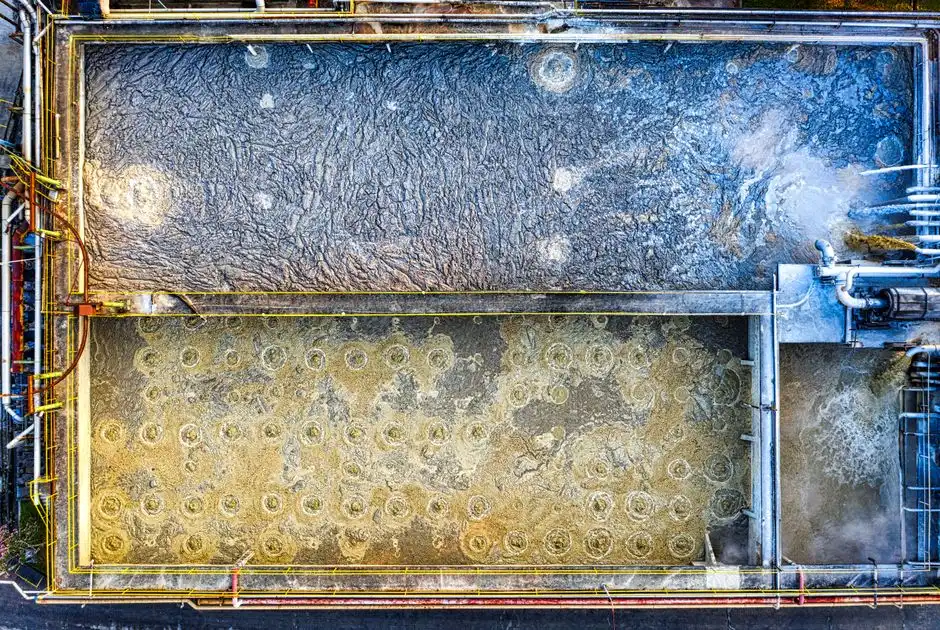
A DAF that is correctly designed can still fail if it is asked to do the work of upstream screening or downstream sludge handling. Spent broth carries grain husks, ruptured cell debris and slug loads of antifoam, so a rotary mechanical bar screen on the headworks protects the float tank from rags and large clumps that would otherwise accumulate in the launder. Coagulation with ferric chloride or aluminium sulphate runs best in a 6.5–7.5 pH window, which is most reliably delivered by an automatic chemical dosing skid on the floc-tank feed line rather than by manual adjustment.
On the back end, the floated yeast-rich sludge is a thick, protein-rich stream that quickly becomes a return-loop problem if it is not dewatered; a plate and frame filter press converts it to a handleable cake with a defined disposal route. DAF effluent still contains soluble BOD from residual sugars and amino acids, and any plant that is targeting water reuse or a stringent discharge consent should plan for biological polishing such as an MBR downstream. The DAF design for dairy wastewater guide walks through comparable buffer-tank and floc-train conventions, and the 2026 DAF engineering specs and decision framework covers the broader parameter set; the HydropureWater DAF system itself is the unit that ties these pretreatment and post-treatment steps together.
Sizing Checklist and Common Pitfalls
Three pitfalls account for most underperforming yeast-plant DAFs. Pitfall one is copying an oil-and-gas or food-oil DAF datasheet without re-checking air solubility at 30–60 °C; warm broth quietly de-rates the saturator and shifts the micro-bubble size distribution, so recycle and saturator sizing must be re-validated on the actual feed. Pitfall two is ignoring antifoam and silicone carryover; because antifoam is engineered to suppress bubble attachment, jar tests with the actual broth — not a synthetic — are non-negotiable before the A/S ratio and flocculant dose are frozen. Pitfall three is under-specifying the sludge path; a unit that lifts 94% of TSS still produces a thick float, and the downstream dewatering train must be sized for that peak solids rate (Xen et al., 2025).
The sizing checklist itself is short and is meant to be ticked off during a feasibility study:
- Measure TSS, BOD₅ / COD, temperature, pH and antifoam type on the broth over one to two production weeks, including a CIP rinse day.
- Run jar tests and a bench-flotation rig to fix the A/S ratio, coagulant dose and flocculant dose on the actual feed.
- Decide the bubble-generation mode — conventional saturator versus YADAF — on footprint, H₂O₂ handling and the presence of a downstream oxidation step (Xen et al., 2025).
- Confirm that headworks screening, automatic chemical dosing, sludge dewatering and any biological polishing are in scope and sized to peak flow, not average flow.
For broader context on parameter conventions across food and beverage streams, the DAF for starch wastewater design guide covers a comparable warm, high-suspended-solids feed.
Frequently Asked Questions
What bubble size and A/S ratio does a yeast-plant DAF actually need?
Conventional pressurised-recycle DAF targets 10–100 µm micro-bubbles nucleated at particle surfaces through a pressure-reduction valve on the recycle stream (Wikipedia, 2026), and YADAF generates a different in-situ bubble size distribution that should be characterised during any pilot (Xen et al., 2025). The A/S ratio is a design lever, not a fixed default, and must be derived from the measured TSS, the target float-solids concentration and the bench-flotation result; the designer should request a bubble-size distribution curve from any pilot run rather than rely on a vendor's single-number guarantee.
How much does a dissolved air flotation system for a yeast plant cost?
The research evidence does not include a published price for a yeast-plant DAF, so any number a buyer is quoted should be tied back to a defined scope — flow envelope, A/S ratio, recycle configuration and
Frequently Asked Questions
What air-to-solids (A/S) ratio should a DAF be designed at for yeast wastewater?
For yeast wastewater, the design air-to-solids (A/S) ratio is typically specified between 0.02 and 0.06 mg air per mg of suspended solids. Yeast cells are biological solids with a density close to water; therefore, achieving a sufficient air-to-solids ratio is critical to ensure enough microbubbles attach to the yeast flocs to overcome their neutral buoyancy.
Is yeast-assisted DAF (YADAF) a proven alternative to a conventional pressurised DAF saturator?
While experimental methods like YADAF involve using biological processes to generate gases for flotation, it is not currently a standardized industrial alternative to pressurized DAF saturators. Conventional systems using recycle-stream pressurization at 400 to 600 kPa remain the industry standard for reliability, as they allow for precise control of bubble size distribution, typically targeting 30 to 50 microns for optimal yeast capture.
How much TSS removal can I expect from a DAF on a baker's yeast or yeast extract stream?
With proper chemical conditioning using cationic polymers or coagulants, a well-designed DAF system can achieve total suspended solids (TSS) removal efficiencies ranging from 85% to 95%. In yeast extract streams, where protein content is high, removal efficiency is highly dependent on pH adjustment to the isoelectric point of the yeast proteins, typically between pH 4.0 and 5.0.
What jar tests should I run before specifying a DAF for yeast wastewater?
Before specification, you should conduct bench-scale flotation tests using a graduated cylinder and a portable pressure saturator to determine optimal dosage rates for coagulants and flocculants. Specifically, perform a dose-response study for cationic polymers to identify the minimum dosage required to achieve a clear subnatant, and measure the rise rate (velocity) of the yeast floc, which typically ranges from 0.2 to 0.5 meters per minute.
Which DAF supplier and capacity range fits a mid-scale yeast plant, and what lead time should I plan for?
Mid-scale yeast facilities typically require DAF units with hydraulic loading rates between 50 and 200 cubic meters per hour, depending on the specific organic load of the fermentation broth. Major global suppliers including Evoqua, Veolia, and Nijhuis provide modular units within this capacity range; current industry lead times for custom-fabricated stainless steel DAF systems generally range from 20 to 32 weeks depending on material availability and automation requirements.