What "Critical UPW Parameters" Actually Mean in 2026
Critical UPW parameters represent the combined set of water-quality limits and the hydraulic and material conditions maintained continuously inside a recirculating distribution loop, rather than just at the polishing outlet (wxwatertech, 2026). The quality envelope is anchored by five governing Type 1 references: SEMI F63 for semiconductor water quality, ASTM D5127 for electronics and semiconductor UPW, ASTM D1193 Type I, ISO 3696 Grade 1, and CLSI-CLRW for clinical-laboratory water (Axeon, wxwatertech, 2026).
Resistivity above 18.2 MΩ·cm at 25°C is the maximum theoretical resistivity of pure water; any measurable drop signals ionic contamination and serves as the primary guard rail (wxwatertech, 2026). The same 18.2 MΩ·cm water can still carry up to 50 ppb of non-ionic TOC, which is why resistivity and TOC must be monitored as independent parameters (wxwatertech, 2026). Treating "parameters" as only the polishing-outlet numbers is a common spec-side mistake because the loop itself defines the final chemistry.
Point-of-Use Quality Targets: The SEMI F63 and ASTM D5127 Envelope
The parameter table below defines the envelope the distribution loop must deliver at every point of use, rather than exclusively at the polishing skid outlet. All values come from the SEMI F63 / ASTM D5127 parameter set documented in current industry references (Axeon, 2026; wxwatertech, 2026).
| Parameter | Specification | Measurement Method |
|---|---|---|
| Resistivity | >18.2 MΩ·cm at 25°C | Inline temperature-compensated conductivity meter |
| TOC (baseline) | <1 ppb (µg/L) | UV-persulfate oxidation |
| TOC (3nm / 2nm nodes) | <0.5 ppb | UV-persulfate oxidation |
| Silica, dissolved | 0.2-1.0 ppb (ng/L) | ICP-MS |
| Silica, colloidal | 0.3-2.0 ppb (Axeon range); typically set <0.3 ppb at advanced-node point-of-use | ICP-MS |
| Particles >0.05 µm | <0.3 particles/mL | Inline laser particle counter |
| Bacteria | <1 CFU/100 mL | Membrane filtration |
One ambiguity in the publicly available Axeon table requires clarification in any 2026 spec. The table lists a 0.3-2.0 ppb colloidal silica range, while SEMI F63 point-of-use targets for advanced fabs are typically set below 0.3 ppb at the tool (Axeon, 2026). Treat that range as a feed-side diagnostic band and require the vendor to commit to a point-of-use number against the named standard rather than the broad range. The same point applies to particles: the Axeon headline figure of "<1 particle/mL" is the SEMI F63 general limit, but the loop must hold <0.3 particles/mL above 0.05 µm (Axeon, 2026).
Distribution-Loop Design Variables That Protect the Parameter Envelope
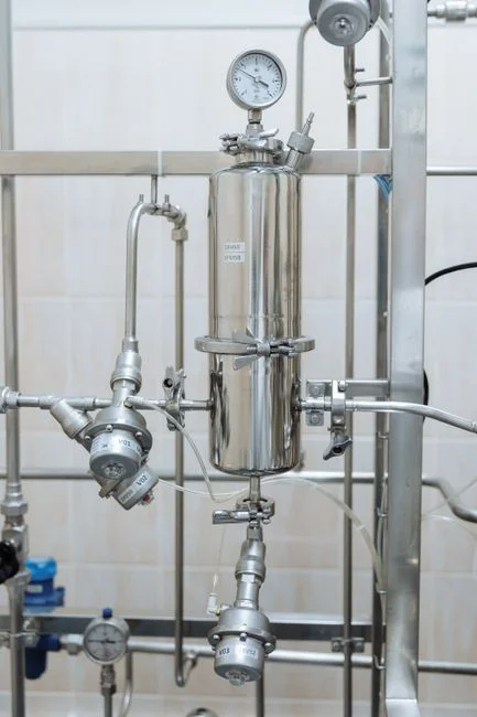
Distribution-loop design dictates the final water quality because ultrapure water is an aggressive solvent. A static storage tank absorbs CO₂ from the air, forms carbonic acid, and drops resistivity below 1 MΩ·cm within hours, making continuous recirculation through a polishing loop mandatory (wxwatertech, 2026). Getting the polishing skid from 10-15 MΩ·cm at the EDI outlet to the 18.2 MΩ·cm benchmark requires tight control of dissolved CO₂, high-purity non-leaching polishing resin, and short residence times inside the distribution loop (wxwatertech, 2026).
For sub-7nm lines, distribution-loop design — material selection, velocity, and dead-leg elimination — is as critical as the treatment equipment itself (wxwatertech, 2026). High-purity non-leaching materials (PFA, PVDF, PP) prevent the loop from adding organics, silica, or boron to the stream the polishing skid has just cleaned. Inline monitors must be temperature-compensated: raw resistivity changes with temperature, and uncompensated readings at 18°C versus 25°C can produce a false pass or false fail (wxwatertech, 2026). Spot testing from a sample port provides a data point rather than a process record; continuous resistivity and TOC monitoring are required at the polishing outlet and at critical use points (wxwatertech, 2026). Polishing-side equipment selections that feed the loop include EDI polishing stacks for the distribution loop and dual-wavelength 185/254 nm UV for TOC reduction.
Sampling, Alarms and Recovery-Time Targets
The alarm architecture mirrors the parameter hierarchy. Inline TOC analyzers using UV-persulfate oxidation provide real-time organic-carbon data at the 1-ppb detection level, which is the resolution the spec demands (wxwatertech, 2026). Particle and bacteria limits are the leading indicators of a distribution-loop breach — they drift before resistivity or TOC does, so alarm setpoints should be sized to catch excursions on particles and bacteria first, with resistivity and TOC acting as confirmation (Axeon, 2026). Recovery time — how fast the loop returns to spec after a tool-side upset — is governed by loop volume, recirculation rate, and polishing skid capacity, and is the single KPI a fab should negotiate with the UPW system vendor (wxwatertech, 2026). The throughput scale is set by fab consumption of 2-4 million gallons of municipal water per day and per-wafer UPW use of 4.5-7 L/cm² for advanced facilities (Axeon, 2026).
Decision Matrix: Which Parameter to Tighten First at Sub-7nm Nodes
Engineers must follow a specific order of operations when tightening parameters as a fab moves from baseline SEMI F63 to 3nm/2nm nodes. The table below maps each parameter to its primary risk driver and indicates whether the tightening occurs at the polishing skid, in the loop, or both.
| Priority | Parameter | Risk driver at advanced nodes | Where to tighten |
|---|---|---|---|
| 1 | TOC (<0.5 ppb at 3nm/2nm) | Organic residues drive patterning defects; industry target drops below 0.5 ppb (Axeon, 2026) | Polishing skid (185/254 nm UV + low-TOC IX resin) plus loop material control (wxwatertech, 2026) |
| 2 | Colloidal silica (POU <0.3 ppb) | Wafer-defect sensitivity scales with node shrink; fix a POU number, do not rely on the 0.3-2.0 ppb range (Axeon, 2026) | UF polishing and loop material selection (Axeon, 2026) |
| 3 | Particles >0.05 µm (<0.3/mL) | Polishing skid plus loop shedding/absorption govern the count (Axeon, 2026) | Final 0.2 µm filters plus loop velocity and dead-leg control (Axeon, wxwatertech, 2026) |
| 4 | Bacteria and endotoxin | Tied to sanitisation frequency; life-science UPW adds 5 kDa UF plus sterile filtration on top of 185/254 nm UV (wxwatertech, 2026) | Loop sanitisation cycle and point-of-use filtration (wxwatertech, 2026) |
Resistivity remains at >18.2 MΩ·cm at 25°C across all nodes; it must be held rather than tightened. The tightening decisions are made on TOC, silica, particles, and biology in that order at sub-7nm.
Writing the RFQ: A Loop-Side Checklist for Suppliers
The procurement spec should be written so that suppliers quote against the loop, not only the polishing skid. Use this checklist in the RFQ to ensure each vendor commits to the same loop-side numbers. A spec built only from the parameter table leaves the loop variables — velocity, dead-leg length, recovery time, materials — to be decided after the order is placed, which leads to the installation of undersized loops.
- Name the standards the loop must satisfy: SEMI F63, ASTM D5127, ASTM D1193 Type I, ISO 3696 Grade 1 (Axeon, wxwatertech, 2026).
- Provide the feed-water analysis. Municipal feed requires 1,400-1,600 gallons to make 1,000 gallons of UPW, so feed quality drives the pretreatment design (Axeon, wxwatertech, 2026).
- Request point-of-use guarantees for resistivity, TOC, dissolved and colloidal silica, particles >0.05 µm, and bacteria, with the measurement method named for each (Axeon, 2026).
- Ask the vendor to specify the loop material of construction (PFA, PVDF, PP), the recirculation velocity, the maximum dead-leg length, and the expected recovery time after a tool-side upset (wxwatertech, 2026).
- Confirm that the polishing skid includes continuous temperature-compensated resistivity and UV-persulfate TOC monitoring at the polishing outlet and at the critical use points (wxwatertech, 2026).
Pretreatment-side equipment to reference in the RFQ includes an industrial RO system for UPW pretreatment and a multi-media pretreatment filter upstream of the UPW train. For facility-level planning beyond the loop, see the UPW scale-up and tool-count growth guide, the semiconductor fab wastewater treatment in Nagoya reference, and the semiconductor pretreatment compliance near Durham, NC guide.
Frequently Asked Questions
What resistivity should a UPW distribution loop hold at the point of use?
>18.2 MΩ·cm at 25°C per SEMI F63 and ASTM D5127, measured with a temperature-compensated inline conductivity meter (Axeon, 2026).
What TOC limit applies at advanced nodes?
<1 ppb baseline; tighten to <0.5 ppb for 3nm and 2nm nodes (Axeon, 2026).
Why does the loop drop resistivity even when the polishing skid is healthy?
Static UPW absorbs CO₂ from the air, forms carbonic acid, and drops resistivity below 1 MΩ·cm within hours; continuous recirculation through a polishing loop is required (wxwatertech, 2026).
Which inline instruments are mandatory on the distribution loop?
Temperature-compensated resistivity meters and UV-persulfate TOC analyzers at the polishing outlet and at the critical use points (wxwatertech, 2026).
What should we include in an RFQ to avoid an undersized UPW loop?
Include the feed-water analysis, the daily volume, the point-of-use quality targets with the SEMI/ASTM reference, the loop material, the recirculation velocity, the maximum dead-leg length, and the recovery-time KPI. For cost decisions, request a recurring-consumable line item (resin, UV lamps, RO membranes, EDI stacks) with service life to compare the total cost of ownership across vendors. Regarding compliance, require the vendor to name the standard each parameter is measured against