What 'High-Purity Water' Actually Means in a Data Center
In a data center, 'high-purity water' actually means two very different things: cooling-tower makeup water (typically TDS 500–1,500 mg/L, hardness below 200–400 mg/L as CaCO₃, suspended solids 10–25 mg/L) and IT-side polishing-loop water that may need RO/EDI-grade permeate. A modern 2026 high-purity system for data center cooling usually chains a reuse or raw-water pretreatment stage (multimedia, DAF or UF at ~0.03 µm) with a primary RO, then a polishing RO or EDI stack for the high-purity loop, and recycles 70–90% of cooling-tower blowdown on-site. Per an Open Engineering 2026 LCA, reclaimed municipal water cuts freshwater demand but raises treatment energy and GWP roughly twofold versus freshwater, while still delivering the bulk of the water-saving benefit.
The cooling-tower loop is an open, evaporative recirculating system where scale, corrosion, fouling and microbiological growth (especially Legionella) are the failure modes. A widely cited specification for this loop sets TDS at 500–1,500 mg/L, hardness under 200–400 mg/L as CaCO₃, suspended solids at 10–25 mg/L, pH 6.5–8.5, alkalinity 50–200 mg/L as CaCO₃ and heterotrophic plate count (HPC) below 10,000 CFU/mL. These values define what cooling-tower-grade water looks like; they are not the same thing as 'high-purity' in the IT-loop sense.
The IT-side loop is a different hydraulic circuit. It feeds rack CDUs, single-phase liquid-cooling manifolds, chip-level cold plates and, in some designs, the secondary side of rear-door heat exchangers. There, mineral deposition, biofilm and electrochemical attack on copper and aluminum surfaces are the risks, and the practical answer is RO permeate pushed further with EDI to a resistivity class typically associated with 18.2 MΩ·cm ultrapure water. U.S. data centers consume about 200 billion gallons of water per year, with cooling at 80–90% of demand, so the cooling-tower envelope still dominates the facility's water footprint even when the IT loop is a smaller volumetric share.
| Parameter | Cooling-tower makeup (floor spec) | IT-side polishing loop (target spec) |
|---|---|---|
| TDS | 500–1,500 mg/L | Near-zero (RO/EDI permeate) |
| Hardness (as CaCO₃) | <200–400 mg/L | Effectively zero |
| Suspended solids | 10–25 mg/L | Sub-micron; absolute UF barrier upstream |
| pH | 6.5–8.5 | Neutral, controlled at polishing skid |
| Alkalinity (as CaCO₃) | 50–200 mg/L | Negligible after RO/EDI |
| Biological / HPC | <10,000 CFU/mL | Non-detectable; non-oxidizing program |
| Resistivity | Not specified | Approaching 18.2 MΩ·cm class |
Source Water Options and Why Reuse Now Wins
Four source categories now compete for the data-center makeup slot: freshwater from a municipal potable network, treated municipal wastewater, industrial wastewater from a co-located plant, and on-site streams such as cooling-tower blowdown and RO reject. The City of Phoenix operates a dedicated recycled water distribution system serving multiple data centers, and that model is the benchmark most other U.S. water-stressed metros are now copying. Treated wastewater typically costs 30–50% less than potable water in most markets, and direct municipal agreements can lock the price in against drought volatility, while potable commercial rates have risen 43% in a decade, putting 50–100 MGD facilities above $500,000 per year before discharge fees.
On-site blowdown recovery is the fastest-payback option for a hyperscale retrofit. One Texas facility recovers 2.5 million gallons of cooling-tower blowdown per month, cutting municipal draw by 35% and eliminating blowdown discharge fees — a 70–90% on-site reuse rate is achievable with the right head-of-train design. The scale of the broader opportunity is large: a 2014 Stillwell & Webber study (cited in the 2026 Open Engineering LCA) projected that reclaimed municipal wastewater could save up to 300 million gallons per day of freshwater withdrawals across Texas power plants.
Reclaimed water is not free, and the LCA makes the tradeoff explicit. A wastewater scenario has about twice the GWP of the freshwater case, with treatment energy responsible for roughly 80% of the gap. In a UF+RO reuse scenario, wastewater treatment energy grows to over five times that of freshwater, but improved cycles of concentration reduce blowdown and chemical consumption, narrowing the net GWP penalty — especially under a decarbonizing grid, where a system commissioned today and operated through 2050 will spend most of its life in conditions where the reuse penalty is negligible while the water savings accrue at full value.
Cooling-Tower Makeup Specification vs High-Purity Polishing-Loop Specification
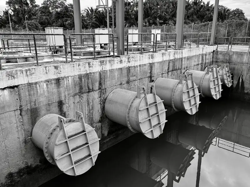
The two loops are not the same problem. The cooling-tower spec is set by physics inside an evaporative system: you can tolerate modest hardness and TDS as long as scale, corrosion, fouling and biological growth are managed. The S5 cooling-tower envelope — TDS 500–1,500 mg/L, hardness under 200–400 mg/L as CaCO₃, SS 10–25 mg/L, alkalinity 50–200 mg/L as CaCO₃, HPC below 10,000 CFU/mL, pH 6.5–8.5 — is the working window. Genclean-S tablet data from a 2-MW edge site on treated municipal wastewater shows HPC below 1,000 CFU/mL, non-detectable Legionella on quarterly testing, and corrosion rates under 2 mils per year, demonstrating that the cooling-tower envelope is reachable without aggressive oxidizer chemistry.
The IT-side loop has to prevent mineral deposition, biofilm and electrochemical attack on heat-exchange surfaces that are smaller, hotter and harder to clean than a cooling-tower fill. The practical requirement is RO permeate, and usually a polishing stage on top — either a second pass of RO or a continuous EDI stack. Hitting the cooling-tower spec is about chemistry control; hitting the IT-side spec is about removing the chemistry.
One feed can serve both only if a polishing skid is added on a slip-stream, otherwise the two loops must be designed and treated as separate hydraulic circuits. The LCA makes the operational case for separating them: the UF+RO reuse scenario uses over five times the energy of a freshwater feed, but the resulting water quality lets the cooling loop run at higher cycles of concentration, which is where the blowdown and chemical savings come from. The polishing train matters more in a reuse scheme, not less.
| Driver | Cooling-tower makeup | IT-side high-purity loop |
|---|---|---|
| Primary failure mode | Scale, corrosion, fouling, Legionella | Mineral deposition, biofilm, galvanic attack |
| Key control parameters | TDS, hardness, alkalinity, HPC, pH | Resistivity, TOC, silica, dissolved O₂, bacteria |
| Acceptable chemistry | Defined envelope (see prior table) | Near-zero dissolved ions |
| Treatment goal | Condition the water | Strip the water |
| Typical equipment | Softener + chemical program; or RO/NF on reuse | RO + EDI (or 2nd-pass RO) on a slip-stream |
Designing the Reuse-to-Polishing Train
A defensible 2026 reuse-to-polishing train is a six-step architecture. The exact equipment choice at each step is driven by source water, target loop and discharge rules, and the steps line up as follows.
Step 1 — Pretreatment. A multi-media filter drops TSS to protect downstream membranes; on high-solids industrial or municipal reuse feeds, a DAF unit ahead of the filter is the right choice for oils, colloids and floatables. S5 documents a 7-MW site that pairs a self-cleaning mechanical screen with UF to absorb suspended-solids spikes from upstream manufacturing without fouling downstream membranes.
Step 2 — UF polishing. A hollow-fiber UF system at roughly 0.03 µm acts as an absolute barrier ahead of RO, accepting turbid source water while protecting RO membrane life. S5 reports 7-MW and 10-MW sites using this UF configuration for variable-quality industrial and municipal feeds, with the 10-MW case processing 150 GPM through UF followed by NF that drops hardness from 350 mg/L to 120 mg/L as CaCO₃.
Step 3 — Primary RO. An industrial RO system is the workhorse for dissolved-solids reduction. A primary/secondary RO configuration on municipal wastewater achieves 88% overall water recovery and 98% TDS reduction — the working benchmark for sizing high-recovery RO on a data-center reuse feed. Where source TDS exceeds RO concentrate discharge limits, RO with concentrate recovery is the configuration that lets a permit issue at all.
Step 4 — Polishing. A continuous EDI polishing stack pushes RO permeate to high-purity, near-ultrapure resistivity for IT-side loops without acid/caustic regeneration or neutralization waste. RO-only polishing is acceptable for cooling-tower makeup but is not sufficient for tight IT-side specifications where resistivity in the 18.2 MΩ·cm class is the target.
Step 5 — Disinfection. A non-oxidizing program — silver-zinc ionization, ClO₂ or UV — protects the high-purity loop from biofilm without the corrosion and disinfection-byproduct risk of free chlorine. A on-site ClO₂ generator gives the operator a controllable oxidant residual that does not damage RO membranes or IT-loop metallurgy. The 2-MW edge site referenced earlier hit HPC below 1,000 CFU/mL and non-detectable Legionella on quarterly testing with a silver-zinc tablet program; a PLC-controlled chemical dosing skid is the usual way to deliver this consistently at hyperscale.
Step 6 — Blowdown recovery. Route cooling-tower blowdown back to the head of the train. S5 reports that 70–90% on-site recovery is achievable, with the Texas hyperscale case processing 2.5 million gallons per month and reducing municipal draw by 35%. For deeper treatment-train design on blowdown specifically, the cooling-tower blowdown treatment guide walks through the unit operations, and a related manufacturing water-reduction engineering guide covers the broader site-water balance. For data-hall process wastewater, the data hall process wastewater engineering guide is the right reference, and the polishing-loop distribution technology guide covers the distribution-side details of 18.2 MΩ·cm loops.
Energy, Cycles of Concentration and the Honest Tradeoffs
Raising cycles of concentration (COC) is the single most powerful operating lever a data-center water engineer has: it cuts blowdown volume, reduces chemical consumption, and shrinks the size of the polishing skid. The tradeoff is that higher COC pushes TDS, hardness and corrosion risk up inside the loop, which is why the S5 cooling-tower envelope (TDS up to 1,500 mg/L, hardness up to 400 mg/L as CaCO₃) is the operating window, not the target.
The Open Engineering 2026 LCA quantifies the energy and GWP side of this tradeoff honestly. In the UF+RO reuse scenario, wastewater energy is over five times the freshwater case, but improved cycles of concentration reduce blowdown and chemical consumption enough that the net GWP penalty narrows over the asset life, especially under a decarbonizing grid. The same study puts the indirect water penalty of reuse at approximately 0.93 L/m³ from upstream electricity and chemical inputs — a real number, but less than 0.1% of the direct freshwater displacement, so it does not flip the conclusion.
On the equipment side, nanofiltration sits between UF and RO and uses 30–40% less energy than RO for hardness and multivalent-ion removal (S5), which is why NF is often the right intermediate stage on a reuse feed. EC (electrocoagulation) is the right answer when source conductivity exceeds 1,000 ppm, particularly for high-TDS industrial wastewater or concentrated cooling-tower blowdown; for lower-TDS feeds, mechanical filtration plus the GCAT/Zeoturb train is the lower-energy path.
Regulatory and ESG Constraints You Cannot Skip in 2026
Water reuse is now a permitting issue, not a sustainability nice-to-have. The World Resources Institute classifies 17 U.S. states as high or extremely high water stress, and those states host roughly 40% of U.S. data center capacity. Santa Clara County, California already requires new data centers above certain capacity thresholds to use recycled water for cooling operations, and similar rules are emerging in Arizona, Nevada, Florida and Texas.
California's Title 22 framework is the de facto benchmark for recycled-water quality in cooling-tower makeup, and other states either reference EPA guidelines or maintain their own programs. Permit timelines run 6–18 months depending on the jurisdiction and project complexity, which means a reuse project has to start the regulatory track in parallel with engineering, not after it. Discharge permits (NPDES for surface water, pretreatment permits for sanitary sewer) are the second leg of the same regulatory conversation, and concentrate management often drives the equipment choice more than the influent quality does.
On the ESG side, corporate water-stewardship commitments and reporting frameworks have made water intensity a directly citable KPI. A reuse train is a hard number — m³/yr of freshwater displaced, % blowdown recycled, kWh/m³ of treatment energy — that procurement, regulators and ESG raters can all read off the same set of meters. The honest disclosure also includes the upstream water penalty (roughly 0.93 L/m³ in the LCA) so the reported footprint reflects reality rather than the marketing line.
How to Choose the Right High-Purity Train for Your Site
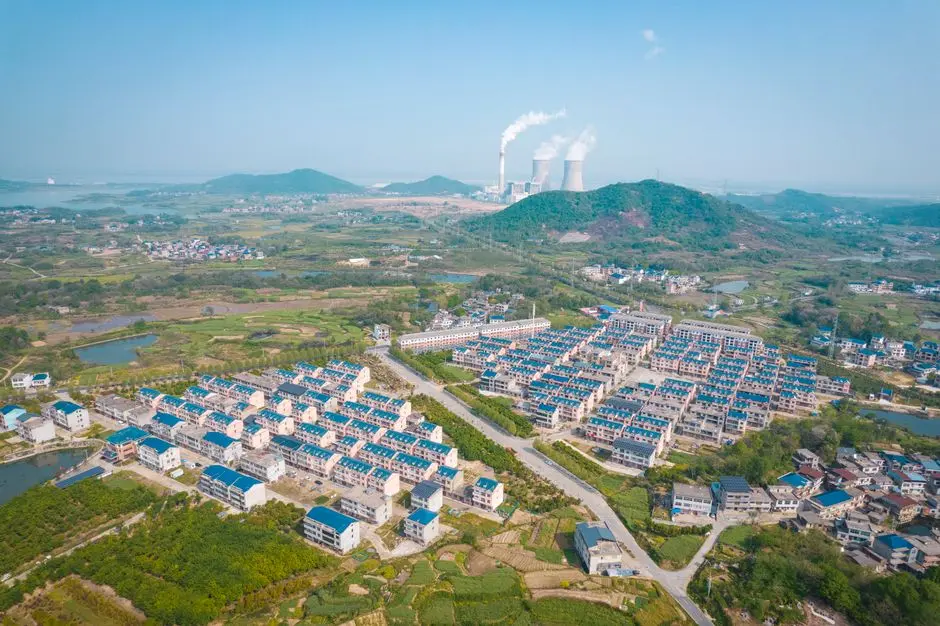
The decision framework below converts the article into five rules a facilities or process engineer can apply during front-end engineering. Each rule ties to a specific number or constraint in the research so the choice is defensible at a design review.
- If the IT loop needs near-ultrapure resistivity, plan for RO + EDI on a slip-stream regardless of source water. If the requirement is only cooling-tower makeup, RO or even NF may be sufficient.
- Match the membrane stage to source TDS. For source water TDS above 1,000 mg/L (typical of brackish or industrial reuse), specify RO with concentrate recovery; for TDS below 1,000 mg/L, NF can cut energy by 30–40% while still meeting hardness and scale targets.
- For on-site blowdown recovery at hyperscale sites, target 70–90% reuse and design the head of the train to accept variable-quality return streams without fouling downstream membranes.
- For water-stressed regions, design to the highest-recovery configuration the permit will allow — the 88% recovery / 98% TDS reduction benchmark from the municipal-wastewater case is the realistic upper end — and budget for 6–18 months of permitting in parallel with engineering.
- For ESG reporting, track both freshwater displacement (m³/yr) and the indirect upstream water penalty (about 0.93 L/m³) so the disclosure reflects the real water footprint rather than the headline number.
Frequently Asked Questions
What is the difference between cooling-tower makeup water and high-purity IT-loop water in a data center?
Cooling-tower makeup is evaporative-loop water controlled to TDS 500–1,500 mg/L, hardness below 200–400 mg/L as CaCO₃, suspended solids 10–25 mg/L and HPC under 10,000 CFU/mL. IT-side high-purity water is RO permeate, often polished further with EDI toward 18.2 MΩ·cm-class resistivity. The two loops are treated as separate hydraulic circuits, with the polishing skid fed from a slip-stream off the main RO.
How much does a high-purity reuse train cost, and what drives payback?
Equipment and engineering costs are site-specific; the research gives the operating economics. Treated wastewater typically costs 30–50% less than potable water, and potable commercial rates are up 43% in a decade, putting 50–100 MGD facilities above $500,000 per year before discharge fees. On-site blowdown recovery of 70–90% is achievable, with one Texas case recovering 2.5 million gallons per month and reducing municipal draw by 35% while eliminating blowdown discharge fees. A buyer should request a site-specific water balance and a unit-cost stack (m³ of freshwater displaced, $/m³ of discharge avoided, kWh/m³ of treatment energy) from each vendor before pricing equipment.
How do I pick a supplier for a UF/RO/EDI polishing train?
Match the equipment to the source water and the loop specification first, then qualify the supplier on documented reference installations at similar feed TDS and similar recovery targets. Ask for site references with published recovery (the 88% / 98% TDS reduction case is the working benchmark) and for an energy figure in kWh/m³ of permeate; ask how the train handles feed variability, because the 7-MW and 10-MW sites in the research were specifically designed for variable-quality industrial and municipal feeds.
What is the realistic permit timeline for a reuse project in a water-stressed U.S. state?
Approval timelines run 6–18 months depending on the jurisdiction and project complexity, and that clock starts when the permit application is filed. Because the regulatory track and the engineering track are usually sequential in practice even when they are scheduled in parallel, a project that needs water online in 18 months should be in pre-permit discussion with the regulator before FEED is locked.
Related Equipment
- industrial RO system — specifications, capacity range, and technical data