Why Electrodialysis Design Starts with Feed, Not Stack Size
Electrodialysis (ED) is an electro-membrane separation process in which ions migrate through alternating cation-exchange membranes (CEMs) and anion-exchange membranes (AEMs) under an applied DC voltage, producing a depleted diluate stream and a concentrated brine stream in adjacent compartments (MDPI Membranes review, 2020). The same repeating CEM–AEM cell architecture can desalinate, fractionate monovalent from divalent ions, or split water into acid and base; therefore the technology should be treated as a family of unit operations rather than one. Selection is driven by target ions, target product (treated water vs. recovered acid/base vs. fractionated salt), and the feed's fouling propensity — not by the size of the stack that a vendor has on the shelf.
Before any cell-pair count is calculated, lock down the feed envelope. The minimum defensible set is total dissolved solids (TDS), full target ion list (cations and anions, including trace species), scaling indices for Ca²⁺, Ba²⁺, Sr²⁺ and SiO₂, organic load (COD/BOD), total suspended solids, oil and grease, temperature, and pH range across the operating season. Where any of these are unknown, a site-specific pilot on the actual feed — not literature defaults — is the only defensible basis for a full-scale design, because the MDPI Membranes review (2020) explicitly notes that membrane behavior is characterized by both static methods (membrane potential) and dynamic methods (current efficiency and chronopotentiometric measurement), and those responses shift with the real feed matrix. Treat the feed envelope as a hard gate: it is cheaper to characterize than to redesign a stack.
The Electrodialysis Family: Seven Variants, One Decision Matrix
Pick the variant by treatment objective first; the feed characteristics then decide which engineering refinements (membrane grade, reversal cadence, pretreatment train) are needed. Conventional ED uses a repeating CEM–AEM cell pair to produce a diluate and a concentrate, and is the baseline configuration for brackish desalination and TDS reduction. Electrodialysis reversal (EDR) reverses electrode polarity on a timed cycle to dislodge foulants and scale from membrane surfaces, and is commonly practiced for fouling mitigation (MDPI Membranes review, 2020). Bipolar membrane electrodialysis (BMED) adds bipolar membranes to a monopolar stack and splits water at the bipolar interface, generating acid and base streams simultaneously.
Selectrodialysis (SED) deploys monovalent-selective membranes to preferentially pass monovalent ions and reject divalent species, enabling fractionation of mixed ionic streams — for example, isolating chloride from sulfate. Electrodialysis metathesis (EDM) uses a four-compartment repeating unit containing two AEMs and two CEMs to perform salt-to-salt conversions, useful in brine valorization. Electrodeionisation (EDI) fills the diluate compartment with ion-exchange resin, polishing RO permeate to ultrapure water without acid or caustic regeneration, which is directly relevant when ED is paired with downstream RO. Reverse electrodialysis (RED) runs the ED stack in reverse to harvest electricity from a salinity gradient rather than consume it. The decision matrix below maps treatment objective to the appropriate variant; the prose above gives each variant's working principle.
| Treatment objective | Recommended variant | Defining feature | Typical product stream |
|---|---|---|---|
| Reduce TDS / brackish desalination | Conventional ED | Repeating CEM–AEM cell pair | Low-TDS diluate, concentrated brine |
| Scale- or biofouling-prone feed | EDR | Periodic polarity reversal | Diluate, brine, foulant-laden flush |
| Generate acid and base from salt | BMED | Water dissociation at bipolar membrane | Acid stream + base stream + residual salt |
| Fractionate monovalent from divalent ions | SED | Monovalent-selective membranes | Monovalent-rich stream, divalent-rich stream |
| Salt-to-salt conversion / brine valorization | EDM | Four-compartment repeating unit (2 AEM + 2 CEM) | Two reconfigured salt streams |
| Polish RO permeate to ultrapure water | EDI | Ion-exchange resin in diluate compartment | Ultrapure water, no chemical regenerant |
| Recover energy from a salinity gradient | RED | Reverse of ED; electricity out, not in | Electricity, two mixed-salinity effluents |
Pretreatment Design: What ED Will and Will Not Tolerate
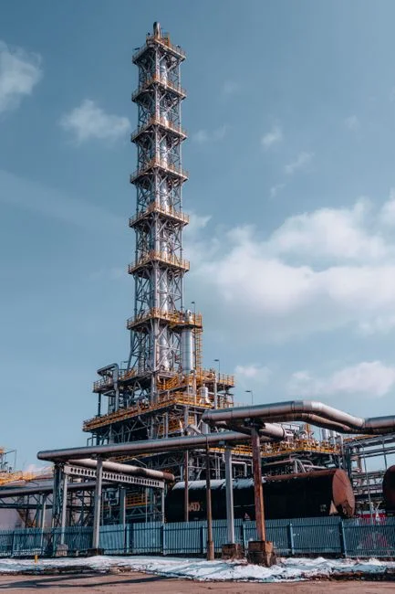
ED tolerates dissolved ions but fouls on the same species that foul RO: suspended solids, colloidal silica, oil and grease, organic macromolecules, and hardness scales. Pretreatment is therefore not optional — it is part of the membrane's operating envelope. A defensible pretreatment train for industrial ED duty is mechanical screening first, followed by a DAF unit for oil, grease, and colloidal removal ahead of ED, then a multi-media filter to protect the ED stack for SDI reduction, finishing with cartridge filtration (typically 5 µm) immediately upstream of the stack. Scale control is a parallel track: feed pH adjustment, antiscalant dosing, hardness pre-softening, or — when the variant is compatible — running EDR so that scale is periodically flushed by reversed flow.
For organic-bearing industrial feeds, the 2026 Ren et al. study in J. Environ. Manage. (415:130583) on desalination of hypersaline ethylene glycol wastewater shows that EG leakage through CEM and AEM was always approximately equal under the conditions tested, because charge conservation, ion hydration numbers, and binding energy combine to make the two membranes contribute in roughly equal measure. The same study found that applied voltage and initial organic and salt concentrations materially affect leakage. The engineering consequence is that membrane selection on its own is not a sufficient mitigation in organic feeds: operating voltage and the upstream organic/salt envelope must also be controlled in design, and the fouling-control plan must address both membrane types, not only the one that fouls fastest.
Stack, Membrane, and Spacer Specification
The stack specification fields on a purchase order are capacity-driving and should be set as a coherent set, not as independent line items. Cell pair count, membrane active area per pair, and the stack hydraulic configuration (sheet-flow vs. spacer-filled) determine capacity; the number of cell pairs is the primary lever on throughput, while active area sets the per-pair flux. Membrane selection is the second most consequential decision after variant choice: standard CEMs and AEMs for general desalination, monovalent-selective grades for SED, bipolar membranes for BMED, or specialty fouling-resistant grades for high-organic feeds.
Membrane characterization should reference both static methods (membrane potential) and dynamic methods — electrodialysis current-efficiency tests and chronopotentiometric measurement (MDPI Membranes review, 2020) — to avoid relying on a single supplier data sheet. The electrode assembly (typically titanium with precious-metal coatings) and the electrode-end compartment design set the upper bound on applied voltage; this must be specified together with the power supply's voltage and current limits so that the DC bus rating matches the membrane window. Spacer geometry — woven vs. non-woven, thickness, open area — controls pressure drop, boundary-layer thickness, and particulate fouling propensity, and is not interchangeable across vendors. Where pressure drop or boundary layer is a known risk, request a vendor calculation stamped against the design feed and the design recovery.
Operating Envelope: Voltage, Current Density, and Recovery
Run the stack below limiting current density, with a design margin that absorbs feed variability and seasonal temperature swings. The MDPI Membranes review (2020) describes limiting current density and chronopotentiometric measurement as the standard tools for locating that ceiling; the working point should sit clearly under it, not at it. Per-pass water recovery is governed by the concentrate stream's saturation indices, and pushing recovery without modeling CaCO₃, CaSO₄, BaSO₄ and SiO₂ scaling is the most common cause of unscheduled shutdowns on industrial ED systems.
Voltage drop per cell pair and overall stack voltage determine the power supply rating and the DC bus architecture; the engineer must verify that applied voltage, not just current, stays within the membrane vendor's window at the design point. The 2026 Ren et al. study further reports that applied voltage is one of the operating parameters that materially affects organic leakage through both CEM and AEM in hypersaline organic feeds. For organic-bearing duty, voltage selection is therefore a product-quality decision — it changes what passes through the membranes — and not just an energy decision. Use the same operating-envelope calculation to set the CIP trigger thresholds: when stack resistance rises or product conductivity drifts at a fixed voltage, the recovery or current-density window has to be re-evaluated before the next ramp.
Fouling, Cleaning, and the Case for Electrodialysis Reversal
Treat cleaning as a designed-in process step, not as unplanned maintenance. EDR with periodic polarity reversal is the default fouling-mitigation strategy and is commonly practiced for scaling- and biofouling-prone feeds (MDPI Membranes review, 2020). The cleaning-in-place (CIP) regime must be specified alongside the stack: acid wash for inorganic scale, alkaline or surfactant wash for organic and biological fouling, with frequency tied to pressure-drop and stack-resistance trending rather than a fixed calendar.
For organic-bearing industrial feeds, the 2026 Ren et al. evidence indicates that reducing organic leakage requires modifying both CEM and AEM simultaneously, which means the fouling-control plan should address both membrane types, not just the one that fouls fastest. An automated antiscalant and CIP chemical dosing system tied to the trending signals keeps the chemistry consistent and removes a manual-operations failure mode. Spacer and membrane age tracking — pressure drop, stack resistance, and product conductivity drift — must be built into the control system; replacing a membrane set on observed drift is cheaper than running a stack past its service life and into a forced outage.
Scale-Up, Integration, and Risk Register
Scale ED systems up in four defensible steps: lab single-cell, bench stack, pilot containerized unit, then full-scale skidded plant. Each step must validate the variant choice, not just the throughput — confirming on the real feed that the membranes, reversal cadence, and CIP chemistry actually hold the operating window. Integration with upstream biological or physico-chemical treatment must be confirmed: ED and EDR work best as a polishing or fractionation step after suspended solids, oil/grease, and bulk organics have been removed, often with an EDI stack for RO permeate polishing within an ED/RO hybrid train and RO membrane elements paired with the ED system when reuse-quality water is the goal.
The risk register below is the short list an engineer should carry into a vendor meeting or an internal design review.
| # | Design risk | Why it bites | Mitigation in the spec |
|---|---|---|---|
| 1 | Concentrate scaled past saturation | Forces unscheduled shutdown; damages membranes | Model CaCO₃, CaSO₄, BaSO₄, SiO₂ at design recovery; cap recovery accordingly |
| 2 | Under-sized pretreatment | SDI or oil breakthrough fouls stack within days | Specify DAF + multi-media + 5 µm cartridge; set outlet SDI and oil limits |
| 3 | Membranes specified only by TDS | Selectivity for the target ion is wrong | Demand selectivity data against the actual ion list, not generic NaCl |
| 4 | Temperature effects ignored | Resistance and limiting current shift seasonally | Re-rate the design point at min and max feed temperature |
| 5 | EDR paired with incompatible CIP chemicals | Polarity reversal exposes new membrane face to wrong chemistry | Demand a CIP compatibility list that covers both polarities |
| 6 | EDI specified without continuous current | Resin in the diluate compartment will not regenerate | Confirm continuous current supply and resin service interval in the spec |
| 7 | Electrode replacement cost under-estimated at full scale | Major OPEX surprise mid-life | Request electrode life data and replacement cost in the RFQ |
Hand-off items to demand from the ED supplier at the RFQ stage: membrane age warranty, limiting current density at design temperature, CIP chemical compatibility list, spare-membrane set lead time, and reference plants operating on a feed matrix similar to yours. For context on operating cost benchmarks, see the nanofiltration and RO maintenance cost benchmark for 2026, and for cross-technology process selection see the industrial wastewater treatment cost and technology comparison for 2026 and the pharmaceutical wastewater treatment process selection for 2026.
Frequently Asked Questions
How do I choose between ED, EDR, BMED, and SED for an industrial wastewater duty?
Start with the treatment objective, not the hardware. Use the decision matrix in Section 2: pick conventional ED for brackish TDS reduction, EDR when the feed is scaling- or biofouling-prone, BMED when the goal is acid and base generation, and SED when the goal is monovalent-from-divalent fractionation. After the variant is fixed, the feed envelope then drives membrane grade, reversal cadence, and pretreatment depth.
What influent parameters must I provide to an ED supplier to get a defensible design?
Provide the full set from Section 1: TDS, the complete ion list (cations and anions), scaling indices for Ca²⁺, Ba²⁺, Sr²⁺ and SiO₂, organic load (COD/BOD), suspended solids, oil and grease, temperature range, and pH range. Without that set, any supplier design is built on assumptions — request a written assumption list and flag any parameter the supplier has defaulted from literature rather than your data.
Is EDR always better than conventional ED for industrial wastewater?
No. EDR adds valves, instrumentation, and operating complexity, and it pays back only when the feed is scaling- or fouling-prone. On clean brackish feeds and on RO-polishing duty, conventional ED is simpler and cheaper to operate. Decide by feed propensity, not by default.
What should a realistic ED pilot scope look like before committing to a full-scale system?
Run a pilot on the actual feed, not a synthetic substitute, long enough to capture seasonal and feed-batch variability. Capture pressure drop, stack resistance, product conductivity, current efficiency, and concentrate scaling indices across the full operating window, and use the dataset to verify the variant, membrane grade, and CIP regime before issuing a full-scale PO. A pilot that only confirms throughput is not a defensible basis for a membrane-process design.