The Regulatory Stack for a Wichita Petroleum Discharger
Petroleum refineries, crude oil terminals, and gas processing plants discharging to the sanitary sewer in Sedgwick County operate inside a four-layer regulatory stack, and the engineer designing the pretreatment train has to satisfy all four at once. At the top sits EPA's Clean Water Act §307(b), which authorizes categorical pretreatment standards for industrial categories; that authority is implemented for petroleum facilities through 40 CFR Part 435, the oil and gas extraction and refining category. Below that, the State of Kansas — through KDHE — holds the delegated NPDES authority, and the City of Wichita holds the pretreatment program permit for the Lower Arkansas Water Quality Reclamation Facility (Plant 2) on the Arkansas River. Plant 2 is the control authority for roughly 200 square miles of service area, and its pretreatment specialists sit inside the plant (per City of Wichita, S1).
Because a petroleum plant is on the 40 CFR Part 435 categorical list, it is a Categorical Industrial User (CIU) and is bound by both the federal categorical standards and the local limits Wichita sets under 40 CFR 403 (per City of Wichita, S1). Categorical limits set the floor (what EPA says every refinery must achieve); local limits set the ceiling on top of that (what Wichita needs to protect the POTW). For pre-application scoping, the Pretreatment Office can be reached at 316.303.8700 or [email protected] (per City of Wichita, S1).
What Pretreatment Limits a Petroleum CIU Must Actually Hit
A refinery discharging to Plant 2 has to design against four pollutant families simultaneously: oil and grease, total suspended solids, phenols, and trace metals — most commonly nickel and chromium from hydroprocessing and desalter service. These are the standard 40 CFR 435 reporting parameters, and they appear again in the categorical discharge limits the refinery has to hit at the monitored outfall. Where the categorical number is silent or generous, the Wichita local limit is the binding number (per EPA Local Limits Development Guidance, S4 framework).
Wichita develops those local limits using EPA's Maximum Allowable Headworks Loading (MAHL) methodology, a five-step process: identify pollutants of concern, collect influent/effluent/sludge data, calculate MAHLs for each pollutant, allocate allowable loadings to controlled sources with a safety factor and growth allowance, and adopt the limits through the public participation process (per EPA Local Limits Development Guidance, S4 §2.2). The limits must protect against pass-through (a pollutant that slips through the POTW into the Arkansas River), interference (a pollutant that disrupts biological treatment), sludge quality (so the biosolids can be land-applied or landfilled), and air emissions from the treatment units. A petroleum CIU is therefore protecting four receptors at once: the river, the sewer, the biomass, and the biosolids (per EPA Local Limits Development Guidance, S4 §3.2.1–3.2.6).
To get on the program a refinery submits an Industrial Waste Survey, completes a Permit Application, and files a baseline monitoring report, with permit fees scaled to the industrial wastewater daily flow rate (per City of Wichita, S1). The table below consolidates the design targets a petroleum CIU is designing against — both the categorical regime and the local limit envelope that sits on top of it.
| Parameter | 40 CFR 435 Categorical Anchor (refinery subcategory, daily max) | Typical Wichita Local Limit (envelope to design against) | Source |
|---|---|---|---|
| Oil & Grease | 15 mg/L (total) at the monitored outfall | ≤ 10–15 mg/L 24-hr composite; visible sheen prohibition | 40 CFR 435.62; S1, S4 |
| Total Suspended Solids (TSS) | 30 mg/L (refinery subcategory) | ≤ 30 mg/L monthly avg, 45 mg/L daily max | 40 CFR 435.62; S4 |
| Phenols (4AAP) | 0.16 mg/L | ≤ 0.1 mg/L monthly avg, ≤ 0.3 mg/L daily max | 40 CFR 435.62; S4 |
| Chromium (total) | 1.0 mg/L | ≤ 1.0 mg/L daily max; site-specific MAHL allocation | 40 CFR 435.62; S4 §5.2.1 |
| Nickel (total) | 1.0 mg/L | ≤ 0.5–1.0 mg/L daily max; MAHL-allocated | 40 CFR 435.62; S4 §5.2.1 |
| pH | 6.0–9.0 standard | 6.0–9.0 standard; slug-control plan required | 40 CFR 403; S1, S4 |
| Flow (per CIU) | Reported monthly | Permit-defined daily max; fees scale to mgd | S1, S4 §4.9.4 |
Source Segregation and API Oil/Water Separation
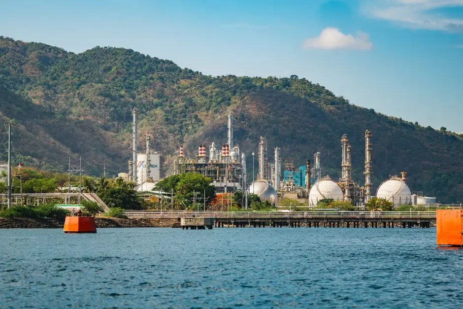
The first engineering decision is where to put the physical barrier between oily process streams and the sanitary sewer. Source segregation is the cheapest load reduction a refinery will ever buy: keep desalter brine, tank draw-off, and ballast water separate from stormwater, non-contact cooling water, and boiler blowdown, and route each stream to its own treatment. The hydraulic and pollutant load on the downstream train drops immediately, and the segregated high-oil streams can often be recycled on-site or shipped off as a recoverable product rather than paid for as wastewater treatment (per typical refinery process-design practice and EPA Local Limits Development Guidance §3.2.12 on hazardous-waste decision points, S4).
The first unit operation after segregation is the API oil/water separator — a gravity basin that drops free oil out of the wastewater stream. A well-designed API separator with a corrugated plate pack typically achieves 30–60 minutes of effective residence time, removes free oil down to a rough envelope, and hands off an effluent suitable for the next stage of emulsified-oil and suspended-solids polishing (per typical refinery design references). Corrugated plate interceptors (CPIs) are the more compact modern variant: higher surface area in a smaller footprint, easier to retrofit, and the standard choice for a 50–500 m³/day refinery stream where space is at a premium.
One decision point the program will press on: segregated streams above a defined oil concentration may be classified as hazardous and routed off-site rather than to the POTW, and that decision is typically made at the source-segregation step rather than at the DAF (per EPA Local Limits Development Guidance §3.2.12, S4). For emulsified oil and fine suspended solids that survive the API step, a DAF system for refinery wastewater is the standard next unit operation.
DAF and Equalization: The Workhorse Step for Wichita Refineries
Dissolved air flotation is the canonical unit operation between the API separator and biological polishing at a petroleum CIU. The mechanism is straightforward: recycle water saturated with air is depressurized inside the DAF contact chamber, generating a cloud of 20–80 micron micro-bubbles that attach to oil droplets and suspended solids and float them to the surface as a float layer that is mechanically skimmed off. With proper coagulant and flocculant conditioning, a DAF can deliver oil and grease below ~10–15 mg/L and TSS below ~30 mg/L — the envelopes the 40 CFR 435 and local limit table demands (per typical refinery DAF design references).
The DAF catalog the engineer is most likely to specify is the DAF line, with 13 standard models covering 4–300 m³/h, automatic skimming, and a proven record in petrochemical and municipal pre-treatment duty (per HydropureWater DAF product catalog). For a 50–500 m³/day refinery stream, that is one or two DAF units with redundancy, sized off the peak hourly flow rather than the daily average. Chemical conditioning is the part of the DAF that actually drives performance: coagulant (typically a cationic polyaluminum chloride or ferric chloride) is dosed at 50–150 mg/L, followed by a high-molecular-weight anionic flocculant at 1–5 mg/L, fed from a PLC-controlled coagulant and pH dosing skid that takes its signal from a flow-paced transmitter on the DAF inlet (per typical refinery chemical-conditioning design and EPA pretreatment control mechanisms, S4 §6.9).
Equalization is the second half of this workhorse step. A surge tank sized to 4–8 hours of peak refinery flow smooths slug loads from batch tank draws and desalter dumps, stabilizes pH, and gives the downstream biological step a feed it can actually treat. Without equalization, the DAF float layer can swing wildly and the biological reactor downstream can lose its mixed-liquor suspended solids during a slug (per typical refinery flow-equalization design and EPA Local Limits Development Guidance §6.9 on control mechanisms, S4).
Biological Polishing and Final Filtration
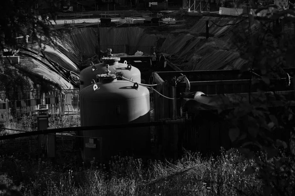
The biological step is what lets a refinery confidently meet dissolved organics, residual phenols, and any ammonia limits that the local limit envelope carries. Two standard choices: conventional activated sludge (CAS) and membrane bioreactor (MBR). MBR has become the more common selection for new refinery pretreatment because it delivers a tighter effluent — typically TSS below 5 mg/L and turbidity below 1 NTU — which protects any downstream reverse osmosis unit a refinery might add later for water reuse. The tradeoff is higher capital cost and more aggressive aeration control, but for a 50–500 m³/day stream the operating cost premium is small relative to the reduced footprint and the consistent effluent quality. The MBR biological polishing stage handles residual COD, phenols, and ammonia in a single compact unit.
Wichita's regional treatment chain provides useful context for the design. The city operates 4 wastewater treatment facilities with primary, secondary, and advanced treatment plus disinfection, and 56 lift stations running 24 hours a day (per City of Wichita Water Resource Recovery, S5). A refinery pretreatment train is the first half of a two-stage system: the refinery's biological step is the "advanced pretreatment" that protects Plant 2's secondary treatment from pass-through and interference, and Plant 2's secondary treatment is what actually produces the Arkansas River discharge. The Wichita NELAP-certified lab analyzes 50+ daily samples across the four city plants, and the documentation standard a CIU should plan to match is NELAP-grade chain-of-custody (per S5).
Solids handling closes the loop. The DAF float and the MBR waste-activated sludge are dewatered together on a plate and frame filter press to roughly 18–22% dry solids, suitable for off-site disposal or, depending on the metal content, landfill. A sludge dewatering filter press sized to the daily float plus waste-activated sludge volume is the standard finishing step, and the cake quality directly ties back to the EPA sludge-quality-based AHL methodology (per EPA Local Limits Development Guidance §5.2.3 and §6.18, S4).
The Permit and Self-Monitoring Package a Wichita CIU Files
The paperwork trail for a Wichita CIU runs in this order: submit an Industrial Waste Survey, complete the Permit Application, file a baseline monitoring report, and then start the 24-hour composite sampling program for the 40 CFR 435 categorical parameters. The Pretreatment Office commits to a 2–4 week review window for a Special Use Discharge Permit, and that window is the practical buffer the engineer should plan around for any new or modified discharge stream (per City of Wichita, S1).
Self-monitoring is not optional. The CIU files periodic compliance reports, maintains chain-of-custody for every composite sample, keeps flow and pH records on the continuous monitors, and allows Pretreatment Program specialists to inspect the facility on demand. Wichita's enforcement authority includes administrative fines and, in the worst case, disconnection from the sewer — a step the city reserves for chronic noncompliance (per City of Wichita, S1). The control mechanisms the program can require are not just numeric limits: the package also includes best management practices (BMPs), a slug control plan, accidental discharge prevention procedures, and a baseline monitoring report — all of which sit inside EPA's "control mechanisms" category and are the same categories Wichita uses in its permit template (per EPA Local Limits Development Guidance §6.9, S4).
For a 50–500 m³/day refinery wastewater stream, the practical equipment package to specify in the permit application is: API/CPI separator → equalization basin with PLC-controlled pH adjustment → DAF system for refinery wastewater with PLC-controlled coagulant and pH dosing → MBR biological polishing stage → multimedia filtration → UV or chlorination disinfection → sludge dewatering filter press for solids. If the refinery is pursuing water reuse, add a brackish-water RO unit downstream of the MBR and size the MBR for a tighter envelope (TSS < 5 mg/L, turbidity < 1 NTU). If the stream is at the low end (50 m³/day) and the refinery is not pursuing reuse, a CAS basin with a sand filter can substitute for the MBR and reduce capital cost. The 40 CFR 435 categorical numbers, the Wichita local limits, and the MAHL allocations all stay the same — only the equipment selection between biological and filtration changes. Engineers building the analogous treatment train at a mining/metals or semiconductor facility will recognize the same skeleton; see the parallel mining/metals pretreatment guide for Kansas and the semiconductor pretreatment guide for a CIU for category-specific overlays. For the equalization-basin pH control loop specifically, the pH control fundamentals for pretreatment systems primer is the right reference doc.
Frequently Asked Questions
Is a petroleum refinery discharging to the sanitary sewer in Wichita a Categorical Industrial User?
Yes. Petroleum refining is a listed category under 40 CFR Part 435, so any refinery, terminal, or gas plant discharging to Plant 2's sanitary sewer is a Categorical Industrial User and is subject to both the federal categorical standards and the City of Wichita's local limits under 40 CFR 403 (per City of Wichita, S1, and EPA Local Limits Development Guidance, S4).
What is the Special Use Discharge Permit review window at the Wichita Pretreatment Office?
Two to four weeks. The City of Wichita Pretreatment Office asks that Special Use Discharge Permit applications be submitted at least 2–4 weeks before the planned discharge, which is also the practical buffer for any new or modified stream from a CIU (per City of Wichita, S1).
How does Wichita set its local limits, and how do those limits interact with the 40 CFR 435 categorical numbers?
Wichita uses EPA's Maximum Allowable Headworks Loading (MAHL) methodology: identify pollutants of concern, collect influent/effluent/sludge data, calculate MAHLs, then allocate allowable loadings to controlled sources with a safety factor and growth allowance (per EPA Local Limits Development Guidance §2.2, S4). The 40 CFR 435 categorical number sets the federal floor; the Wichita local limit is the binding ceiling on top of it, designed to protect against pass-through, interference, sludge quality violations, and air emissions at Plant 2.
Who do I contact at the Wichita Pretreatment Office for a pre-application scoping call?
The Pretreatment Office is reachable at 316.303.8700 and at [email protected] (per City of Wichita, S1). The office is housed at the Lower Arkansas Water Quality Reclamation Facility (Plant 2) on the Arkansas River, and the staff also runs an annual industry workshop.