
Why TOC Is the Yield-Limiting Parameter in FPD UPW
US flat panel display (FPD) fabs in 2026 must hold ultrapure water (UPW) Total Organic Carbon at low-single-digit ppb — typically ≤1–5 ppb at the point-of-use — to protect array, color filter and cell rinse steps from particle, watermark and ionic defects. Compliance is anchored in SEMI E1.2 / SEMI F63 and ASTM D5127 electronics-grade water specifications, with online conductivity-based or UV-persulfate TOC analyzers at the polish-loop and return-loop take-offs providing the continuous evidence yield and reuse teams require.
A single 24-hour TOC excursion at the return loop of a Gen 8.5 fab can scrap 30,000–50,000 panels, depending on which step the contamination reaches. At a color-filter rinse step, an organic-acid spike as small as 3 ppb above baseline will produce visible watermark defects on roughly 4–7% of panels, and those panels are usually caught at the post-cell optical inspection station, after the array stack has already been bonded. By that point the material cost — substrate, color-filter photoresist, spacer, liquid crystal — is sunk; the rework path is to strip the polarizer and re-clean, which doubles the wet-process time and halves the tool's effective throughput for the shift.
FPD UPW looks similar to semiconductor UPW on a spec sheet, but the operating envelope is different. Flow rates are larger — a Gen 8.5 fab consumes 8–12 million gallons of UPW per day (per Hach industry data, 2026), and Gen 10.5 lines push that to 14 million+ — and the tools tolerate slightly larger particle counts because pixel pitch is 50–200 µm versus 3–14 nm at a logic wafer. What the FPD line will not tolerate is organic residue on a color filter, because the residue distorts the liquid-crystal alignment layer and shows as a mura defect that is visible to the end customer.
Four FPD process steps are sensitive enough to drive the spec: (1) array rinse after photoresist strip, (2) color filter rinse after pigment dispersion development, (3) cell rinse before polarizer lamination, and (4) the final DI rinse before glass packaging. TOC is the leading indicator at all four — not conductivity — because low-molecular-weight organic acids from photoresist residue can pass a mixed-bed polisher and only show as a slow conductivity drift hours later. By the time the conductivity traces move, the panels in that time window are already on the line.
2026 TOC Specifications for US Flat Panel UPW
The governing references for FPD UPW TOC in 2026 are SEMI E1.2 (Guidelines for Ultrapure Water Used in Semiconductor Processing, applied by FPD fabs by extension) and SEMI F63 (Guide for Total Organic Carbon Measurement in Ultrapure Water), with the cross-referenced spec coming from ASTM D5127 Type E-1.1 / E-2.1 electronics-grade water. The Type E-1.1 POU ceiling is 1 ppb TOC, and E-2.1 allows up to 5 ppb at the bulk distribution loop outlet; FPD Gen 8.5+ fabs typically write their internal POU limit at ≤1 ppb and their return-loop alarm setpoint at 3 ppb to give the polish loop one residence-time period of corrective action before panels see the water.
2026 expectations have tightened against the 2018–2020 baselines, when 5 ppb POU was acceptable at Gen 6. Three drivers pushed the floor down: higher-resolution panels (4K/8K monitors, tablet and automotive displays) where a 30 µm mura is now customer-visible, the shift to oxide-TFT backplanes which are more sensitive to organic residue at the gate dielectric, and the use of low-temperature polyimide alignment films that absorb trace organics and outgas in the cell. SEMI F63 explicitly recommends online monitoring at the polish-loop outlet and at the return loop, with a measurement floor at least 10× below the action limit — which is why a sub-ppb analyzer is no longer optional.
| Spec point | 2026 TOC target (ppb) | Alarm setpoint (ppb) | Governing standard |
|---|---|---|---|
| Make-up RO permeate | ≤50 | 100 | SEMI E1.2 §6.4 |
| Post-EDI polish outlet | ≤5 | 8 | ASTM D5127 E-2.1 |
| Post-185 nm UV (polish loop) | ≤2 | 3 | SEMI F63 §5.2 |
| Point-of-use (POU) | ≤1 | 2 | ASTM D5127 E-1.1 |
| Return loop take-off | ≤10 | 15 | Internal alarm baseline |
| Reuse blend (fab wastewater RO permeate into UPW make-up) | ≤30 | 50 | SEMI F63 + site-specific reuse SOP |
Two clarifications matter when defending the spec to a corporate sustainability team. First, the return-loop limit is set higher than POU because the polish loop has residence time and a UV unit to strip TOC before it reaches the tool. Second, the reuse blend line is its own sampling point: in 2026, most US FPD fabs blend 20–40% treated fab wastewater into UPW make-up to hit reuse targets, and TOC breakthrough on that blend line is the rate-limiting step more often than the front-end RO.
Where TOC Enters — and Leaves — the FPD UPW Train
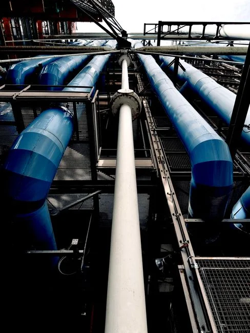
The standard FPD UPW train in 2026 runs: city/municipal make-up → multimedia filter → carbon filter (dechlorination + TOC guard) → cartridge filter → double-pass RO → EDI polish → 185 nm UV (TOC reduction) → mixed-bed polisher → sub-micron filter → POU. TOC enters the train at the make-up, where municipal TOC typically runs 2,000–4,000 ppb, and the carbon filter takes that down to 200–500 ppb before the first-pass RO. The double-pass RO train for FPD UPW make-up rejects 95–99% of the remaining organics, leaving 5–20 ppb at the first-pass permeate and 1–5 ppb at the second-pass outlet, depending on feed TOC and recovery.
The 185 nm UV unit is the primary TOC destruction step. It works by photolyzing low-molecular-weight organics to CO2 and water, and a correctly sized unit delivers 30–60% TOC reduction across the unit, with a nameplate dose of 30–40 mJ/cm². UV output degrades with lamp age: at 8,000–12,000 hours (roughly 12 months of continuous service), 185 nm output drops below 60% of nameplate, and TOC reduction falls off accordingly. This is the most common silent failure mode in FPD UPW and the one the on-shift engineer is most likely to see in the 2 a.m. call.
Four sampling points are mandatory in a 2026 FPD UPW loop, and each requires a different analyzer technology because the sample matrix and the target range are different:
- Post-RO (second pass): 1–10 ppb range, organics-laden sample, online UV-persulfate analyzer with conductivity detection.
- Post-EDI: 1–5 ppb range, low-ionic matrix, online membrane-conductivity analyzer for the lowest detection floor.
- Post-185 nm UV (polish-loop outlet): sub-ppb to 2 ppb, the spec-critical point — dual-analyzer redundancy is now standard.
- Return-loop take-off: variable, up to 10–20 ppb, online UV-persulfate with auto-dilution, plus grab-sample lab TOC weekly.
The EDI polishers downstream of the second-pass RO drop TOC further (typically 0.2–0.5 ppb contribution from resin leachates) but cannot remove urea or low-MW organic acids, which is why the UV stage is non-negotiable. In 2026, a fifth point is becoming standard at large US fabs: the reuse blend take-off, between the fab wastewater RO permeate and the UPW make-up tank. The reason is that, as the FPD fab wastewater treatment design guide documents, urea and other low-MW organics from stripping chemistry survive a single RO pass and will push the reuse blend TOC above 30 ppb if not polished — which then loads the UPW carbon filter and shortens its service life.
Online TOC Analyzer Technologies for Sub-ppb FPD UPW
Three online analyzer technologies are deployed at US FPD fabs in 2026. Each has a different detection floor, response time, and maintenance burden, and the right choice depends on which sampling point the analyzer is protecting. Direct conductivity is the simplest and cheapest method: it measures the conductivity change after UV oxidation of organics to CO2, and it works down to about 1–2 ppb in a low-ionic background. It is adequate at the post-EDI point where the matrix is clean, but it cannot resolve sub-ppb excursions at the polish-loop outlet, and it is fooled by CO2 ingress from atmospheric leak points in the sample line.
UV-persulfate with conductivity detection adds a persulfate oxidizer to the UV stage, which converts more organics to CO2 and gives a detection floor around 0.5–1 ppb with a 4–8 minute response time. This is the workhorse for the post-RO and return-loop points, where the sample is organics-laden and the spec is in the 1–10 ppb range. The trade-off is reagent consumption (persulfate cartridges every 30–60 days) and a larger footprint than direct conductivity.
Membrane-extraction conductivity pulls only the CO2 through a gas-permeable membrane and measures it in a low-ionic receiving stream, eliminating interference from the sample background. Detection floor drops to 0.05 ppb, with a 6–12 minute response, and the method is the only one with enough headroom to verify a ≤1 ppb POU spec against an alarm at 2 ppb. The trade-off is membrane replacement every 6–12 months and a higher unit cost (roughly 1.5–2× UV-persulfate).
| Technology | Detection floor | Response time | Best-fit sampling point | Maintenance burden | Relative unit cost |
|---|---|---|---|---|---|
| Direct conductivity (post-UV oxidation) | 1–2 ppb | 2–4 min | Post-EDI guard, low-priority | Low | $ |
| UV-persulfate + conductivity | 0.5–1 ppb | 4–8 min | Post-RO, return loop | Medium (reagent) | $$ |
| Membrane-extraction conductivity | 0.05 ppb | 6–12 min | Post-185 nm UV polish-loop outlet (POU proxy) | Medium-high (membrane) | $$$ |
| Grab-sample lab (Sievers/GE, Shimadzu) | 0.05 ppb | 8–15 min (offline) | Weekly QA cross-check, audit evidence | Low (operator-driven) | Per-sample |
2026 best practice at Gen 8.5+ fabs is dual-analyzer redundancy on the polish-loop outlet, with one membrane-conductivity and one UV-persulfate unit wired to a voting logic that alarms only when both exceed setpoint. A single failed analyzer on a Gen 8.5 line is a multi-million-dollar-per-day exposure during the window between failure and the next routine grab-sample QA, so the redundancy pays back in months. The four supplier families with documented FPD reference installs in the US are Hach, Sievers (Veolia), METTLER TOLEDO, and Endress+Hauser; analyzer capex for a fully redundant sub-ppb system on the polish loop typically lands in the $180,000–$320,000 range as of early 2026 (HydropureWater field data, 2026).
TOC Excursions: Symptoms, Root Causes, Fixes
When the analyzer alarms at 2 a.m., the on-shift engineer has roughly one residence time — typically 20–45 minutes in a Gen 8.5 polish loop — before the contaminated water reaches the tools. The decision table below maps the four most common symptom patterns to root cause and corrective action. The principle: always check the post-UV polish-loop reading first. If it is flat while the return loop is moving, the cause is upstream carryover from a specific tool or sub-loop, not the UPW train itself.
| Symptom (where, when) | Likely root cause | First check | Fix |
|---|---|---|---|
| Post-UV TOC rises slowly over 4–6 h, polish loop drifts, return loop follows ~1 h later | 185 nm UV lamp aging — output below 60% of nameplate | Lamp age (should be <12,000 h); intensity sensor reading | Replace lamp; verify intensity sensor; baseline the new lamp at startup |
| Post-RO TOC rises sharply within 2 h of a maintenance event | Carbon filter channeling or exhaustion; possible free chlorine breakthrough | Free chlorine at carbon outlet; ΔP across carbon vessel; last backwash date | Backwash carbon; verify free chlorine is <0.1 ppm; replace carbon if ΔP or age indicates exhaustion |
| Return-loop TOC drifts up while polish-loop TOC stays flat | Photoresist or strip-chemistry carryover from a specific tool; sub-loop isolation issue | Sub-loop flow distribution; tool exhaust condensate; rinse-nozzle flow on suspected tools | Isolate sub-loops one at a time; check tool exhaust and rinse-nozzle flow; verify the tool's strip-chemistry dosing |
| TOC rises only when reuse blend exceeds 40–50% of make-up | TOC / urea breakthrough in the reuse RO train; carbon filter on the reuse line is undersized | Reuse RO permeate TOC; reuse carbon vessel ΔP; UV dose on the reuse line | Increase UV dose on the reuse line; add a polishing carbon on the reuse blend line; or pull the reuse blend back to 30% until the upstream RO recovers. See the 20-year UPW lifecycle cost guide for UV sizing economics |
| TOC excursions coincide with peak fab shifts; conductivity also drifts up | Resin exhaustion on the mixed-bed polisher or EDI module | EDI current and voltage; mixed-bed conductivity; resin age | Regenerate or replace mixed-bed resin; service EDI module; verify RO membrane replacement and integrity testing is current on the second pass |
One pattern that catches even experienced engineers: a TOC rise that correlates with morning startup, not steady-state operation. That is almost always 185 nm UV lamp warm-up, not a real excursion. Most 2026-vintage analyzers have a warm-up lockout; if yours does not, write a SOP that suppresses the alarm for the first 30 minutes after lamp restart. Also confirm the sample line is polypropylene or PVDF, not PVC — the UPW piping material and TOC leach-rate guidance documents that PVC sample lines can contribute 0.5–2 ppb TOC on their own, which will mask real sub-ppb excursions.
Frequently Asked Questions
What is the 2026 TOC limit for UPW in a US flat panel fab?
The widely accepted 2026 FPD POU TOC limit is ≤1 ppb at point-of-use, anchored to ASTM D5127 Type E-1.1 electronics-grade water, with the polish-loop outlet specified at ≤2 ppb per SEMI F63 §5.2 and the post-EDI bulk outlet at ≤5 ppb per ASTM D5127 E-2.1. Gen 8.5+ fabs write their internal alarm setpoints 1–2 ppb above the action limit to give the polish loop one residence time to recover before panels see the water, and the return-loop alarm is typically set at 10–15 ppb because the polish loop is designed to strip TOC before the water reaches the tools.
Which online TOC analyzer technology should I use at the polish-loop outlet?
Membrane-extraction conductivity is the only technology with a detection floor (≈0.05 ppb) low enough to verify a ≤1 ppb POU spec against a 2 ppb alarm setpoint. UV-persulfate with conductivity detection (≈0.5–1 ppb floor) is the standard workhorse at the post-RO and return-loop points, where the spec is 1–10 ppb and the sample is organics-laden. 2026 best practice at Gen 8.5+ fabs is dual-analyzer redundancy on the polish-loop outlet — one membrane and one UV-persulfate, with voting logic — because a single failed analyzer is a multi-million-dollar-per-day exposure during the gap to the next grab-sample QA.
How much does a 2026 sub-ppb online TOC analyzer system cost?
A fully redundant sub-ppb system on the polish loop — one membrane-extraction unit, one UV-persulfate unit, voting logic, and sample conditioning — typically lands in the $180,000–$320,000 capex range as of early 2026 (HydropureWater field data, 2026), with annual operating cost (reagents, membranes, service) in the $25,000–$45,000 range. The payback against the cost of a single 24-hour excursion — 30,000–50,000 scrapped Gen 8.5 panels, color-filter rework, and yield loss — is typically 2–6 months at a fully utilized fab.
Does SEMI E1.2 apply to flat panel display fabs, or only to semiconductors?
SEMI E1.2 is written for semiconductor processing, but US FPD fabs adopt it by reference in their UPW specifications because there is no equivalent FPD-specific UPW standard and the organic-contamination mechanisms — photoresist residue, strip-chemistry carryover, organic acids from wet etches — are the same. SEMI F63 is the operational guide for TOC measurement in UPW and is applied directly. For fab wastewater and reuse blend design, the relevant cross-reference is the SEMI F63 framework plus site-specific reuse SOPs, documented in the 2026 FPD fab wastewater treatment design guidance.