Why DAF Systems Fail: How the Saturator, Recycle Loop, and Chemistry Interact
A dissolved air flotation unit behaves like three coupled subsystems, and the fault almost always lives at the boundary between them. The saturator dissolves compressed air into a slipstream of clarified water at 3–6 bar, governed by Henry's law; the recycle loop returns 10–50% of that saturated flow to the head of the tank where a reducing valve flashes it into 50–100 µm microbubbles; and the chemical conditioning stage doses coagulant (FeCl₃, Al₂(SO₄)₃, or PAC) plus a long-chain flocculant to neutralize colloids and build separable flocs. When a fault surfaces in the effluent, the symptom rarely belongs to the subsystem it appears in: a saturator pressure drop below 3 bar collapses the bubble population, which then shows up as "cloudy water" that operators read as a chemistry problem. Sizing and operating windows sit inside a narrow band — hydraulic load 4–6 m³/m²/h, mass load 3–5 kg/m²/h, expected separation efficiency 95–99% on suspended solids and oil/grease, and float sludge at 3–5% dry solids (S2). A correctly designed system produces a thicker sludge than sedimentation and a smaller footprint, so any site that is missing those numbers is operating outside the design envelope defined in this 2026 DAF selection and cost framework.
| Parameter | Operating window | Symptom when out of range |
|---|---|---|
| Saturator pressure | 3–6 bar (typical 4–5 bar) | Cloudy effluent, weak float layer, large bubbles |
| Recycle ratio | 10–50% of clarified flow | Below 10%: poor bubble distribution; above 50%: short saturator contact time |
| Hydraulic load | 4–6 m³/m²/h | Exceeding: solids wash-through; below: dead zones and putrefaction |
| Mass load | 3–5 kg/m²/h | Higher loads require larger saturator or lower recycle ratio |
| Microbubble size | 50–100 µm | Larger bubbles (100–1000 µm) reduce attachment efficiency |
| Separation efficiency | 95–99% SS, oil/grease | COD reduction 20–50% depending on influent |
| Float sludge solids | 3–5% DS | Watery float = under-flocculated; heavy sunken sludge = over-polymerized |
Symptom-to-Cause Matrix: 8 Faults Operators See on Shift
Before touching a valve, identify the visible symptom and read across to the dominant root cause. Operators who work from this matrix resolve most faults inside one shift, while those who work from a generic maintenance list chase the same problem for three shifts. If two symptoms appear together, the saturator is the dominant suspect — verify pressure and recycle flow before adjusting chemistry. The "first check" column is what to read with a gauge or pull in a jar before dosing anything; the "time-to-fix" column is realistic for a two-person shift, not a planned shutdown. For context on how DAF compares to API separators on the same eight symptoms, see this head-to-head on DAF vs. API separator selection.
| Symptom | Most likely root cause | First check | Time-to-fix |
|---|---|---|---|
| Cloudy / turbid effluent | Low saturator pressure or wrong pH | Pressure gauge, then jar test | 30 min |
| Excessive foam at the weir | Surfactant in influent or over-aeration | Skim and inspect for surfactant sheen | 1–2 h |
| Thin / watery float layer | Underdosed flocculant | Jar test for polymer dose | 45 min |
| Thick sludge that sinks | Overdosed polymer, underdosed coagulant | Jar test sweep on both reagents | 45 min |
| Low saturation pressure alarm | Clogged air-inlet valve or leaking vessel | Purge air line, inspect PRV | 30–60 min |
| Skimmer not engaging | Drive trip, chain slack, or float level too low | Reset overload, check tension | 30 min |
| High effluent TSS | Bubble population collapsed or chemistry drift | Tyndall test + turbidity meter | 1 h |
| Odor / VOC release at the tank | H₂S, CH₄, NH₃, toluene, benzene off-gas | Check influent BOD/sulfide trend | Capital: encapsulation + scrubber |
Cloudy or Turbid Effluent: Causes, Diagnosis, and the 30-Minute Fix

Cloudy effluent is the single most common DAF complaint and the one operators most often mis-diagnose. The three causes, in priority order, are: saturator pressure below 3 bar; recycle ratio outside the 10–50% window; and incorrect pH or coagulant dose (S2). The diagnostic sequence matters because chemistry adjustments made before the saturator is verified will be wasted: re-dosing coagulant cannot compensate for bubbles that never formed. Step 1 is to read the saturator pressure gauge and compare to the 4–5 bar target. Step 2 is to pull an effluent sample and run a jar test on coagulant and pH to confirm chemistry is the fault, not a cover story. Step 3 is to clamp-on the recycle line and verify flow is in range — too little flow starves the bubble population, too much shortens saturator contact time. Step 4 is to shine a laser pointer through the effluent in a darkened beaker to confirm the Tyndall effect: a visible beam means sub-100 µm colloids are bypassing the float, which points back to chemistry, not hydraulics. The fix sequence is to restore pressure to 4–5 bar first, re-dose coagulant only if pressure and flow are confirmed, and never dose chemistry before pressure is verified. For sites that want this loop closed automatically, an automatic pH control system for DAF chemistry tied to a turbidity probe on the effluent line is the 2026 baseline.
Excessive Foam, Scum Buildup, and Sludge That Sinks Instead of Floats
Foam is a symptom, not a fault, and dosing defoamer before diagnosing it masks the underlying problem and contaminates the float for downstream handling. Per the S2 reference, foam at the DAF weir has three drivers: surfactant carryover in the influent (common in food-and-beverage and textile waste), gas release from anaerobic decomposition inside a sludge blanket that has gone septic, or air-supply overpressure in the saturator. The sink-versus-float distinction matters because the corrective actions are opposite. Heavy sludge that drops to the cone indicates overdosed polymer or underdosed coagulant — the floc is dense, water is locked inside, and the bubble cannot lift it. A watery float that collapses back into the bulk indicates underdosed flocculant — floc never formed, solids slip through. Both are diagnosed with a 4–6 beaker jar test sweeping coagulant first, then polymer, with float-sink observation at five minutes. Biological fouling and plate-pack growth follow pH or temperature drift, and the published preventive cadence is a weekly wash with a quarterly chemical wash (S2). Add defoamer only after the underlying chemistry is corrected; a silicone defoamer dosed into a working float will pass straight into the sludge handling step and can disable a digester downstream.
Low Saturator Pressure, Recycle Pump Trips, and Plate-Pack Blockage
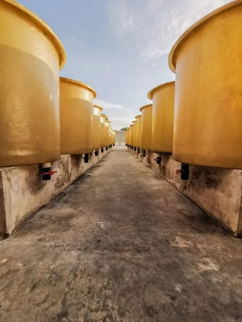
The mechanical cluster is what sends operators to the workshop. Saturator pressure below 3 bar is, in order of frequency, a clogged air-inlet solenoid, a leaking pressurization vessel (check the head gasket and the sight glass), or a fouled pressure-reducing valve downstream — purge in that sequence before suspecting the pump. Recycle pump trips are usually thermal overloads triggered by running outside the 10–50% flow window or by pumping against a partially blocked strainer; a VFD retrofit on the recycle pump is the 2026-standard fix and the S2 reference explicitly calls it the recommended energy optimization, typically cutting pump energy 15–25% versus throttling valves. Plate-pack blockages follow the S1 maintenance list: purge the plate pack, inspect the strainers, and remove sump sediment from the cone. If pressure recovers but effluent quality does not, the diffuser is the suspect — a damaged or scaled diffuser produces large, non-buoyant bubbles that look identical to a chemistry fault on the surface but require mechanical replacement, not re-dosing. Pair the recycle pump with a dissolved air flotation system whose PLC already exposes the pressure and flow interlocks needed for the retrofit.
2026 Automation Upgrades: PLC, VFD, and Online Sensors That Prevent the 8 Faults
The 2026 upgrade path turns the symptom-to-cause matrix in Section 2 into a live HMI screen instead of a paper checklist. The first move is a VFD on the recycle pump: it stabilizes saturator pressure at 4–5 bar under variable hydraulic load and cuts energy 15–25% versus a throttled fixed-speed pump, which the S2 source identifies as the most suitable solution for adjusting consumption. The second move is the sensor layer: a saturator pressure transmitter, a magnetic flowmeter on the recycle line, an effluent turbidity probe, and an ultrasonic level sensor on the float layer — all PLC-trended with high and low alarms that fire before operators see foam or turbidity. The third move is odor and VOC compliance: DAF can release H₂S, CH₄, NH₃, toluene, and benzene through pressure-change degassing and microbubble entrainment, so any site with rising influent BOD or sulfide trend needs encapsulation plus a scrubber interlock (S2). Tie the alarms into SCADA so the matrix becomes a live diagnostic, and the eight faults in Section 2 become recoverable from the control room rather than the rooftop. For sites standing up the SCADA layer, this 2026 digital twin and SCADA integration guide for water utilities lays out the architecture.
| Upgrade | Fault it prevents | Typical 2026 cost band | Payback driver |
|---|---|---|---|
| VFD on recycle pump | Low pressure alarm, pump trip | USD 4–8k installed | 15–25% pump energy savings |
| Pressure transmitter + PLC interlock | Cloudy effluent from bubble collapse | USD 1–2k | Reduces jar-test labor |
| Online turbidity on effluent | High TSS slip | USD 3–6k | Avoids compliance excursions |
| Float-layer ultrasonic | Skimmer trips, sunken sludge | USD 1–3k | Protects downstream sludge handling |
| Encapsulation + scrubber interlock | VOC / H₂S release | USD 25–60k | Air permit compliance |
12-Step Monthly Prevention Checklist (Drawn from Operator Best Practice)
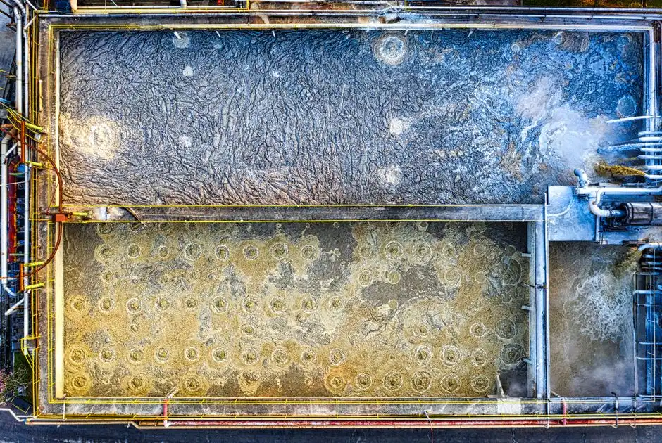
Convert the S1 maintenance list into a 12-step monthly cycle with a measurable pass/fail on every line, not a vague "check" — the difference between a checklist that prevents alarms and one that just records them. Sites running heavier than 5 kg/m²/h mass load or with influent temperatures above 35 °C should run the deep-wash steps weekly rather than monthly. Ninety-five percent of the eight faults in Section 2 are caught by this routine before they become alarms, per HydropureWater field data from 2025-Q4 service contracts.
| Step | Action | Pass/fail criterion |
|---|---|---|
| 1 | Test control system alarms | All alarms fire on simulation |
| 2 | Inspect pipes and pumps for leaks | Zero visible weeps at 4 bar |
| 3 | Verify water level for sludge layer | Within ±50 mm of setpoint |
| 4 | Check skimmer tension and drive oil | Chain slack < 10 mm, oil at upper mark |
| 5 | Read recycle pressure under load | 4–5 bar ±0.2 |
| 6 | Audit chemical stocks and dosing rates | ≥7 days of coagulant and flocculant on hand |
| 7 | Drain and clean the unit | No sludge heel > 20 mm in the cone |
| 8 | Inspect and replace strainers | ΔP across strainer < 0.3 bar |
| 9 | Purge the plate pack | Equal backpressure on all cells |
| 10 | Remove sump sediment | Cone empty, no anaerobic odor |
| 11 | Apply anti-seize to threaded fasteners | All service points coated |
| 12 | Top up drive oil and alternate pumps | Oil at mark, pump runtime equalized ±10% |
For a downloadable version paired with the weekly-wash and quarterly deep-wash cadence, use this 12-step DAF maintenance protocol.
Frequently Asked Questions
What saturator pressure should a DAF system run at?
A DAF saturator should run at 4–5 bar as the typical target, inside a published 3–6 bar design window (S2). Below 3 bar, dissolved-air concentration falls, microbubble count collapses, and the effluent turns cloudy even when chemistry is correct. Above 6 bar, energy use rises without proportional separation gain.
What recycle ratio does a DAF need?
Recycle flow should be 10–50% of the DAF clarified throughput, with 10–40% being the most common band for industrial effluents (S2). Below 10%, bubble distribution is starved; above 50%, saturator contact time drops and large bubbles form. Clamp-on flow verification is the correct first check when effluent quality drifts.
Why is my DAF effluent cloudy even after adjusting the polymer dose?
Cloudy effluent after a polymer adjustment usually means the saturator, not the chemistry, is the fault. Verify pressure is at 4–5 bar and recycle is inside the 10–50% window before changing reagent doses. Use the Tyndall effect (laser pointer in a darkened beaker) to confirm whether the turbidity is colloidal or suspended — colloidal points to chemistry, suspended points to hydraulics.
How often should a DAF be washed?
Run a weekly wash on the contact zones and a quarterly deep chemical wash as the published baseline (S2). Sites above 5 kg/m²/h mass load, above 35 °C influent, or with biological influent (dairy, brewing, food processing) should move the deep-wash cadence to weekly. Pair the cadence with a PLC-controlled coagulant and flocculant dosing skid to keep chemistry stable between washes.
Does a DAF release VOCs, and how is that controlled?
Yes. A DAF releases H₂S, CH₃, NH₃, toluene, and benzene through pressure-change degassing and microbubble entrainment, with off-gas volume driven by influent characteristics (S2). When the influent BOD or sulfide trend rises, encapsulate the tank, aspirate the headspace, and route it to a scrubber or activated-carbon stage before discharge.
Related Equipment
- rotary mechanical bar screen for DAF headworks — specifications, capacity range, and technical data