How an SBR Treats Wastewater in a Single Tank
A sequencing batch reactor (SBR) is a fill-and-draw activated sludge system that performs equalization, biological treatment, and secondary clarification in a single timed-cycle tank. Each cycle runs Idle, Fill, React, Settle, and Draw over 4 to 24 hours, typically with 60 to 90 minutes of aeration, and treats both municipal and industrial wastewater at flowrates of 5 MGD or less.
The 1983 U.S. EPA report on fill-and-draw systems put it bluntly: the SBR is "no more than an activated sludge system which operates in time rather than in space." That single sentence is the entire mental model. Conventional activated sludge (AS) achieves equalization, aeration, and clarification in separate tanks connected by pipes and return-activated-sludge (RAS) pumps. An SBR collapses those unit processes into one vessel and uses a programmable timer — not a piping network — to move the biomass and the wastewater through each process step.
The practical implication for 2026 plant design is footprint and equipment count. Because the SBR never needs a secondary clarifier and rarely needs a primary clarifier (municipal TSS or BOD below 400–500 mg/L is the threshold per the EPA Fact Sheet), the site civil work shrinks. With two or more reactors operated in parallel, one basin settles and draws while another aerates and fills, so the upstream screens, grit removal, and downstream disinfection see an effectively continuous flow even though each individual reactor is strictly batch. Engineers evaluating a submerged MBR system will recognise the same continuous-feed/continuous-discharge outcome, but the SBR gets there with timers and valves rather than membranes.
The Five Operating Phases: Idle, Fill, React, Settle, Draw
Every SBR cycle consists of five sequential steps whose durations the operator programs to match influent strength and discharge permit limits. The order is fixed; the relative time spent in each step is the control lever.
| Phase | Typical Duration | Mixing / Aeration | Primary Process Goal |
|---|---|---|---|
| Idle | Variable (0 to several hours) | Optional mixing | Equalization, sludge wasting, biomass conditioning |
| Fill (static / mixed / aerated) | 1–3 hours | None / mixed / aerated | Floc-former selection, denitrification, or early BOD oxidation |
| React (mixed or aerated) | 1–4 hours | Mixed or aerated | Nitrification, denitrification, biological phosphorus release/uptake, COD oxidation |
| Settle | 0.5–1.5 hours (matches aeration time) | None — quiescent | Solids–liquid separation with no influent or effluent currents |
| Draw | 0.5–1 hour | None | Decant top 20–30% clarified supernatant via floating or fixed decanter |
The Idle step is the operator's most flexible window. Variable idle times give the basin its equalization function, while mixing conditions the biomass and the waste-activated-sludge pump decants excess solids to keep the F:M ratio stable from cycle to cycle. The Fill step has three documented modes that the EPA Fact Sheet describes in detail. Static fill adds raw wastewater with no mixing or air, creating a high-F:M environment that selects floc-forming organisms over filaments and primes the biomass for biological phosphorus removal. Mixed fill blends influent with biomass under anoxic conditions and drives denitrification by using residual nitrate as the electron acceptor. Aerated fill begins aerobic reactions immediately and reduces the aeration time needed in the subsequent React step.
The React step is where the bulk of nitrification, denitrification, and COD oxidation happens. Mixed react drives the anoxic/anaerobic reactions; aerated react finishes the aerobic work and can run long enough to hit ammonia targets below 1 mg/L. Settle follows under completely quiescent conditions, with no inflow or outflow currents to disturb the sludge blanket — a structural advantage over the continuous-flow secondary clarifier in conventional AS. Draw uses either a floating or a fixed decanter to remove only the top 20–30% of the tank, leaving the settled sludge undisturbed. Total aeration time across Fill and React typically runs 60 to 90 minutes per cycle. When chemical phosphorus polishing is needed, an automatic chemical dosing skid can dose aluminium sulfate (alum) during aeration; the resulting precipitate settles with the biomass during Settle.
SBR Design Parameters and Typical Loading Rates
The numbers an engineer needs for a process spec are reproduced almost verbatim from the EPA Fact Sheet's Table 1, which in turn draws on the 1995 AquaSBR Design Manual. The values below are the conventional-load envelope that municipal plants start from; industrial applications push to the high end of each range and almost always require a treatability study.
| Design Parameter | Municipal | Industrial |
|---|---|---|
| Food-to-Microorganism (F:M) ratio | 0.15–0.4 / day | 0.15–0.6 / day |
| Mixed Liquor Suspended Solids (MLSS) | 2,000–2,500 mg/L | 2,000–4,000 mg/L |
| Hydraulic Retention Time (HRT) | 6–14 hours | Varies |
| Treatment Cycle Duration | 4.0 hours | 4.0–24 hours |
Before those numbers are locked, the EPA Fact Sheet requires the designer to characterize the influent for design flow, maximum daily flow, BOD5, TSS, pH, alkalinity, wastewater temperature, TKN, NH3-N, and total phosphorus. Industrial sites add site-specific analytes — colour, salinity, oil and grease, or specific toxicants depending on the process. Where influent TSS or BOD exceeds 400–500 mg/L, the SBR manufacturer will typically recommend a primary clarifier ahead of the basins, because high solids loading interferes with the settle step and pushes wasted-sludge rates above what the downstream digester can absorb.
Plant-level configuration is governed by the requirement that the headworks and disinfection train see continuous flow. A single basin cannot do that because every cycle includes a non-discharging Settle and Draw period. Two or more reactors in parallel are therefore the minimum practical configuration: while one basin is settling and decanting, another is filling and reacting. Larger municipal plants commonly run three or four basins staggered by a quarter or a half cycle to smooth hydraulic gradients on the downstream DAF pre-treatment unit or filtration train.
SBR vs MBR vs Conventional Activated Sludge
For a 2026 procurement brief on a 5 MGD or smaller flow, the head-to-head that matters is between the three biological options a buyer will actually be quoted. The table below compresses the trade-offs into a form an engineer can screenshot into a meeting.
| Criterion | SBR | MBR | Conventional Activated Sludge |
|---|---|---|---|
| Footprint | Compact — no secondary clarifier | Most compact — submerged membranes cut basin volume ~60% | Largest — separate aeration basin + clarifier + RAS pump room |
| Typical effluent quality | Secondary standard; tunable for nitrification + denitrification | Near-reuse quality; <1 µm filtered, low TSS, low BOD | Secondary standard; nutrient removal requires add-on zones |
| Operating complexity | Reliable timers, automated valves, decanter control | Adds membrane cleaning, aeration scour, integrity testing | RAS pump tuning, sludge wasting, clarifier sludge blanket management |
| Nutrient removal flexibility | Retunable in software — cycle phases re-programmed to add N or P removal without new tanks | Retunable but limited by membrane flux at low temperatures | Requires new tanks or anoxic/anaerobic zones to retrofit nutrient removal |
| Energy profile (2026 data) | 30–40% lower energy with intermittent aeration + air-recirculation tuning (Water Environment Research 2026, PMID 42773619) | Higher aeration scour duty plus mixed-liquor pumping | Continuous aeration typically the highest kWh per lb BOD removed |
| Sludge handling | One sludge stream, no RAS | One sludge stream, no RAS | RAS plus waste activated sludge, plus primary sludge if a primary clarifier is used |
The decision usually lands on footprint and discharge permit. If the permit calls for secondary treatment and the site is space-constrained, SBR wins on capital cost and on the absence of a clarifier. If the permit calls for reuse-quality effluent (irrigation, industrial cooling, or <1 mg/L TSS discharge), the buyer migrates to a submerged MBR system and accepts the membrane maintenance burden. Conventional AS still has a place on very large flowrates and on retrofits where the existing aeration basin, clarifier, and RAS piping are already paid for.
Where SBRs Work Best: Municipal, Industrial, and Intermittent Flows
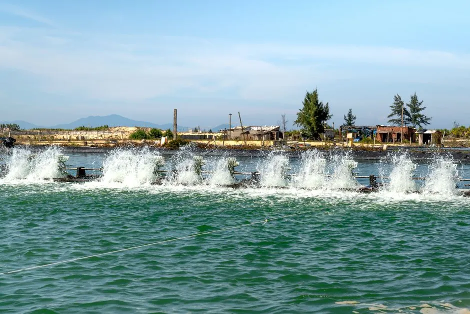
The EPA Fact Sheet's applicability section is the shortest way to frame the use cases: SBRs are typically used at flowrates of 5 MGD or less, on applications characterized by low or intermittent flow, on sites with limited footprint, and where future nutrient-removal retrofits are likely. That covers most small-to-mid municipal plants and a long list of industrial sites.
On the industrial side, SBRs are well documented in food processing, textile, dairy, landfill leachate, and refinery applications — sites where the influent arrives in batches, varies seasonally, or stops entirely on weekends. The same time-segmented cycle that handles diurnal municipal flow handles a 6 am plant startup followed by a 6 pm shutdown. Intermittent-cycle extended aeration system (ICEAS) variants accept continuous inflow through an internal baffle that buffers the feed, which is useful when the upstream process cannot be batched to match the SBR cycle.
Existing conventional AS plants can also be converted to multi-SBR configuration. The retrofit creates a longer sludge age, which reduces downstream sludge-handling volume, and the equalization tanks can sometimes be repurposed as the new SBR basins. For a designer sizing headworks on a new SBR project, a rotary bar screen for solids protection and a DAF pre-treatment unit for oil and grease or high TSS industrial streams are the most common upstream pairings.
Sizing an SBR in 2026: From Flowrate to Blower and Decanter
The EPA Fact Sheet is explicit that sizing is site-specific, but the workflow below is the one a 2026 designer will walk through with an SBR manufacturer. The numbers in the EPA case-study table — flowrates from 0.012 to 5.2 MGD, blower sizes from 1 to 125 HP, basin volumes from 0.021 to 1.359 MG — bound the practical envelope for a U.S. installation.
- Confirm design basis. Document design flow, peak daily flow, BOD5, TSS, temperature, pH, alkalinity, TKN, NH3-N, and TP, plus the NPDES effluent limits. The state agency sets the discharge numbers; the influent numbers come from at least three months of representative sampling for industrial sites.
- Set cycle length and cycles per day. Municipal plants typically run 4-hour cycles (6 cycles/day); industrial plants run 4 to 24 hours depending on treatability. The cycle length drives the HRT envelope of 6–14 hours from EPA Table 1.
- Select MLSS and F:M. Target 2,000–2,500 mg/L MLSS for municipal and 2,000–4,000 mg/L for industrial; constrain F:M to 0.15–0.4/day (municipal) or 0.15–0.6/day (industrial). These two numbers, together with the design BOD loading, fix the required mixed-liquor mass and therefore the basin working volume.
- Calculate basin volume and count. Volume = (flow × HRT) ÷ number of basins in active treatment. Choose at least two basins so one is always settling while another is reacting. A compact packaged sewage treatment plant is the pre-engineered option for sites that fit inside a single skid.
- Size the blowers. Aeration is the largest energy line item. Blower selection needs site elevation, wastewater temperature, and TDS, all of which move the required standard oxygen transfer rate. The 2026 air-recirculation data in the next section changes how those blowers are operated but not how they are initially sized.
- Select a decanter. Floating decanters follow variable water level and tolerate cycle-to-cycle volume changes; fixed decanters are mechanically simpler and cheaper but require a stable operating depth.
Operating Costs, Energy, and 2026 Optimization Options
A 2026 SBR retrofit conversation is dominated by the air-recirculation study published in Water Environment Research (PMID 42773619). The baseline finding is unforgiving: a conventional SBR consumes only 1–2% of the oxygen it supplies and wastes 18–20% in the off-gas. Continuous aeration in that study removed 72.1% of COD and 91.7% of NH4+ in 4 hours, but the energy bill scaled directly with aeration time.
The same paper tested intermittent aeration with a pressurized air-recirculation tank that captures off-gas and returns it to the diffuser. A 5 min on / 5 min off regime held the same COD and ammonia removal while cutting energy 30–40%. Machine-learning optimization (XGBoost for nonlinear pollutant dynamics, SVR for energy use) identified moderate intermittent aeration — 4 to 6 min cycles over a 4-hour total duration — as the best operating envelope.
For a 2026 buyer, the implication is that cycle tuning is software, not new tanks. The blower skid, the automated valves, and the timers on an existing SBR can be reprogrammed and instrumented with a DO probe plus a small PLC to capture most of those savings. Treatability work with the influent in question is still required, but the capex delta is small relative to the OPEX delta over a 10–20 year asset life.
Frequently Asked Questions
What is an SBR in wastewater treatment?
A sequencing batch reactor is a fill-and-draw activated sludge system that completes equalization, biological treatment, and secondary clarification in a single timed-cycle tank. The 1983 U.S. EPA report described it as "an activated sludge system which operates in time rather than in space," meaning the same vessel cycles through Fill, React, Settle, and Draw instead of relying on separate tanks for each step. Source: EPA 832-F-99-073 Sequencing Batch Reactors Fact Sheet.
What is the typical SBR cycle time?
Total cycle time ranges from 4 hours for conventional municipal loads to 24 hours for industrial wastewaters with high strength or toxicity. Within that envelope, the aeration portion of Fill and React typically runs 60 to 90 minutes, and the Settle step usually matches the aeration time to give the sludge blanket enough quiescent period to clarify. Source: EPA Fact Sheet and Wikipedia SBR article.
How does an SBR compare to an MBR for a 5 MGD plant?
For a 5 MGD or smaller plant, an SBR is typically lower capex because it eliminates the secondary clarifier but uses timers and decanters rather than membranes. An MBR delivers near-reuse effluent under 1 micrometre at a smaller basin volume but adds membrane cleaning, aeration scour, and integrity testing to the maintenance scope. The 2026 Water Environment Research paper (PMID 42773619) showed SBRs can reach 30–40% energy savings with intermittent aeration and air-recirculation tuning without adding membranes.
What influent parameters must be characterized before designing an SBR?
The EPA Fact Sheet requires design flow, maximum daily flow, BOD5, TSS, pH, alkalinity, wastewater temperature, TKN, NH3-N, and total phosphorus at minimum. Industrial sites add site-specific analytes such as salinity, oil and grease, colour, or individual toxicants. Where TSS or BOD exceeds 400–500 mg/L, the SBR manufacturer will usually specify a primary clarifier ahead of the basins.