Why Tyler Refineries Are Rethinking Primary Oil-Water Separation in 2026
Tyler and East Texas refineries sit in a subcategory band that most generic buyer's guides ignore: 40 CFR Part 419 Subpart A (Topping) for smaller atmospheric and vacuum distillation operations, and Subpart B (Cracking) for units with catalytic cracking downstream (EPA 2019, Table 2-1). Both subcategories carry production-based Best Practicable Control Technology (BPT) mass limits — pounds of pollutant per 1,000 barrels of feedstock — that are scaled by a size factor and a process-configuration factor, so the same refinery running 80,000 bbl/stream-day with a catalytic cracker has a different effluent envelope than a 30,000 bbl/stream-day topper on East Texas light sweet crude. The 2017 data request the EPA used to build its 2019 Detailed Study pulled Discharge Monitoring Report (DMR) records from 82 refineries, and the eight currently regulated Pollutants of Interest — BOD5, TSS, COD, oil & grease, phenolic compounds, ammonia, sulfide, and total chromium — define the limit set a Tyler refiner must hit (EPA 2019, p. 1-1).
The typical Tyler-area influent is not just "refinery wastewater." It is a blend of desalter brine (high TDS, free and emulsified oil), sour water stripper overhead (sulfide + ammonia), spent caustic (phenolics, high pH), tank farm draw-off (slop oil), and once-through cooling water blowdown (low oil, high TSS from metallurgy scale). The EPA 2019 study flagged an "increase in the number of refineries reporting metals discharges" even though only chromium is in the current ELG (EPA 2019, p. 1-1) — a forward-looking signal that iron- or aluminum-based coagulant chemistry in a future DAF could push metals into the permit's permit-limit analysis, not just the regulated eight. The documented end-of-pipe train is equalization → API separator or baffle plate → biological (activated sludge, aerated lagoon, oxidation pond, trickling filter) → polishing pond or multi-media filter (EPA 2019, §2.1). The DAF-vs-clarifier question is which device sits in the slot between the API separator and biotreatment, and that decision is no longer generic because TCEQ TPDES permits in 2026 are writing mass limits tighter than the federal floor for several of the eight parameters.
What Each Device Actually Does on Refinery Influent
A Dissolved Air Flotation (DAF) unit saturates a pressurized recycle stream with air at 4–6 bar, then releases the pressure in a contact zone where 10–100 micron micro-bubbles nucleate on oil droplets and fine suspended solids. The bubble-particle aggregate has a bulk density below water and floats to the surface in 3–5 minutes, where a skimmer pulls the float off into a sludge hopper. DAFs are designed for streams where the contaminant is lighter than water — free oil, emulsified oil, and FOG — and where hydraulic residence time is too short for a settling tank to do useful work.
A clarifier relies on gravity settling. A conventional circular or rectangular clarifier operates at roughly 1 m/h surface loading rate; a lamella clarifier stacks 60° inclined plates inside the tank to multiply the effective settling area, reaching 20–40 m/h on the same footprint. Solids with specific gravity above 1.0 — sand, catalyst fines, metallurgy scale, iron sulfide precipitate — drop to the hopper and are pumped out as underflow. Clarifiers do not have a physical mechanism for floating oil, so emulsified and free oil either pass through with the effluent or ride the surface as an unskimmed layer that re-entrains downstream.
That physical difference is why a packaged HydropureWater DAF system is the standard answer for refinery desalter and spent-caustic service, where the binding contaminant is oil on water, and why a HydropureWater lamella clarifier is the standard answer for cooling-tower blowdown and clarifier underflow polishing, where the binding contaminant is settleable suspended solids. The Ecologix industrial comparison quantified this split: a DAF on a high-oil stream delivers ~95% FOG removal; a clarifier on the same stream delivers ~70%. Flip the stream to heavy sediment and the clarifier climbs to ~90% TSS removal while the DAF holds the same oil-quality advantage it had before (Ecologix, 2024).
40 CFR Part 419 Limits a Tyler Refinery Has to Hit
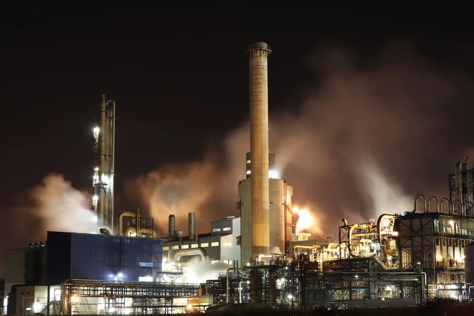
The 40 CFR Part 419 effluent limitations are mass-based, not concentration-only, and that distinction drives equipment sizing. The BPT limit for any parameter is calculated by multiplying a base loading (lb per 1,000 bbl feedstock) by a size factor and a process-configuration factor, both derived from the specific unit capacities present at the refinery (EPA 2019, §2.1). A Tyler topper running 50,000 bbl/stream-day with no catalytic cracker has a different multiplier than a Tyler refinery with a 25,000 bbl/stream-day FCC unit, and the BPT limit — not the technology — is what determines whether the DAF or the clarifier is sized correctly.
For indirect discharges to a publicly owned treatment works, the PSES ceilings are 100 mg/L for oil and grease and 100 mg/L for ammonia as N across all five subparts; PSNS adds 1 mg/L total chromium on top (EPA 2019, Table 2-3). Direct-discharge permits through TCEQ TPDES typically apply the BPT/BAT mass limits plus state water-quality-based effluent limits (WQBELs) on the same parameters, and a Tyler refiner designing in 2026 should assume the more restrictive of the two applies.
| Parameter | PSES ceiling (indirect discharge) | PSNS ceiling (new source, indirect) | Regulated since |
|---|---|---|---|
| Oil & grease | 100 mg/L | 100 mg/L | 1974 (BPT), 1982 (BAT reaffirmed) |
| Ammonia (as N) | 100 mg/L | 100 mg/L | 1974 (BPT) |
| Total chromium | — | 1 mg/L | 1985 BAT revision |
| BOD5, TSS, COD, phenols, sulfide | Mass-based, lb/1,000 bbl feedstock | Stricter mass-based NSPS | 1974/1982 |
Two design implications follow. First, the federal ELG is under active review — the 2019 Detailed Study is the technical basis for the preliminary category review, and the EPA's 2017 data request is the most recent comprehensive influent dataset on record, so a Tyler refiner should design for headroom on all eight parameters, not just the binding one. Second, mass-based limits mean that flow reduction — not just concentration reduction — is a permit lever. A DAF that returns a 2–5% side-stream of thickened float to the front of the API separator increases the upstream load and must be checked against the lb/1,000 bbl math, not the 100 mg/L oil & grease ceiling alone.
DAF vs Clarifier: Head-to-Head on Refinery Duty
The head-to-head below is sized to refinery-strength influent, not to the "oils and greases" generic comparison most top-ranking pages run. Values are drawn from the EPA 2019 Detailed Study influent dataset (Table 5-2) and the Ecologix industrial DAF-vs-clarifier selection benchmark (Ecologix, 2024); hydraulic-loading and footprint numbers are typical engineering ranges for packaged refinery units, not vendor-specific claims.
| Duty parameter | DAF (packaged, refinery duty) | Lamella clarifier (inclined plate, refinery duty) |
|---|---|---|
| FOG / emulsified oil removal | ~90–95% | ~70% |
| TSS removal (primary influent) | ~70–80% | ~85–90% |
| Hydraulic surface loading | 4–25 m/h | 20–40 m/h |
| Footprint at equal flow | Compact, low headroom | ~60–70% of conventional clarifier footprint, taller |
| Chemistry demand | Coagulant (PAC, ferric) + flocculant/polymer | Coagulant often sufficient; polymer optional |
| Sludge / float solids | 3–6% dry solids float; needs plate and frame filter press dewatering | 1–2% dry solids underflow; pumps direct to sludge handling |
| Best-fit stream | Desalter effluent, coker draw-off, tank farm draw-off, refinery stormwater | Cooling-tower blowdown, surface condenser water, post-DAF polish |
Two points to read off the table. First, the DAF's 20–25 percentage-point FOG advantage is the single largest performance gap and is what makes it the primary device when oil & grease is the binding constraint. Second, the lamella clarifier wins on throughput per square meter and on solids handling — its underflow does not need a downstream dewatering step, while DAF float at 3–6% dry solids typically does. That is why the EPA-documented hybrid train — DAF for oil capture, lamella for solids polishing before biotreatment — is the answer most Tyler refiners land on once they run the lb/1,000 bbl mass balance against the 100 mg/L oil & grease ceiling and the BPT TSS limit on the same plant.
When a Tyler Refiner Should Pick DAF, Clarifier, or Both
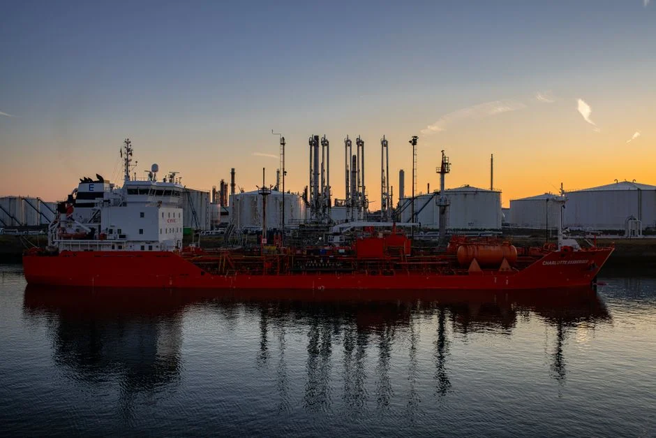
Pick a DAF when free or emulsified oil dominates the stream and the 100 mg/L PSES oil & grease ceiling is the binding constraint. That covers desalter effluent, coker draw-off, tank farm draw-off, and refinery stormwater — the four streams a Tyler refiner handling a blend of East Texas light sweet and Gulf sour crude will see surging in a process upset. The DAF belongs directly downstream of the API separator and ahead of equalization if FOG spikes are short, or after equalization if the upset is sustained.
Pick a lamella clarifier when the stream is mostly cooling-tower blowdown, once-through surface condenser water, or a low-oil solids stream where settleable suspended solids are the binding parameter. The inclined-plate pack makes the lamella clarifier footprint small enough to retrofit into a Tyler refinery that does not have greenfield space, and its underflow can be pumped directly to existing sludge handling without a new dewatering device.
Use a DAF-then-lamella train when the refinery has both heavy FOG loading and tight TSS limits — DAF takes out the oil and a large fraction of the TSS, the lamella polishes the rest before activated sludge. This is also where an automatic coagulant and polymer dosing system pays for itself: the DAF needs a coagulant (PAC or ferric) plus a flocculant to hit 90–95% FOG consistently, and the lamella's lower chemistry demand means the same dosing skid can serve both vessels. Mirror the EPA-documented in-plant BPT measures — sour water strippers for sulfide and ammonia, surface condensers replacing barometric condensers — so the upstream load on the DAF/clarifier train is already reduced before any new equipment is added (EPA 2019, §2.1). For other East Texas industrial decisions, see this Wastewater Requirements When Intel Acquires a Texas Plant (2026 Compliance Guide), and for cross-industry DAF-vs-clarifier context this DAF vs Lamella Clarifier for Mining Wastewater in Wahoo, NE (2026 Buyer's Guide) runs the same matrix for mining duty.
Frequently Asked Questions
Does a DAF fully replace an API separator in a refinery?
No. The DAF and the API separator do different jobs: the API separator removes gross free oil by gravity in a large retention basin, and the DAF targets emulsified oil and fine suspended solids downstream. Replacing the API with a DAF pushes 10–100 micron emulsified oil back into the DAF contact zone at concentrations the saturator cannot handle, and DAF float volumes rise until skimming capacity is the bottleneck.
What is the 40 CFR Part 419 limit for oil and grease for indirect discharge?
Both PSES and PSNS set a 100 mg/L ceiling on oil and grease for indirect discharges across all five subparts of 40 CFR Part 419 (EPA 2019, Table 2-3). Direct discharges through TCEQ TPDES apply the BPT mass limit (lb per 1,000 bbl feedstock) plus any state water-quality-based limits that are more restrictive.
Can a DAF and a lamella clarifier be used together in refinery service?
Yes. The Ecologix industrial comparison confirms that hybrid DAF-then-clarifier trains address complex streams by combining DAF oil removal with clarifier sedimentation (Ecologix, 2024). For a Tyler refiner with both FOG spikes and tight TSS, the DAF hits ~90–95% FOG and the downstream lamella polishes the remaining TSS before biotreatment — the same configuration the EPA 2019 study documents as standard end-of-pipe practice.
How much dry solids does DAF float produce compared to clarifier underflow?
DAF float typically runs 3–6% dry solids and needs a downstream dewatering step such as a plate and frame filter press; clarifier underflow runs 1–2% dry solids and usually pumps directly to existing sludge handling. The DAF float is thicker because the float mechanism concentrates the floated layer, while clarifier underflow is diluted by the bulk water passing through the settler.