

Why the Little Falls, MN POTW Sets the Local Floor for Transportation-Equipment Dischargers
Transportation equipment plants discharging to the City of Little Falls wastewater treatment plant are tying into a 1.1 MGD average-dry-weather activated-sludge facility with a 1.9 MGD average annual design capacity and a 3.42 MGD peak hourly wet-weather flow (cityoflittlefalls.com, accessed 2026). The plant was originally built in 1958 and has been renovated in 1985, 2002, 2005, and 2021 to keep pace with EPA and MPCA effluent and biosolids requirements. Any local limit letter a Morrison County industrial user receives is calibrated against that envelope, not against a generic POTW.
The collection system is approximately 80 miles of sewer main served by 19 lift stations that pump flow up to gravity segments feeding the plant (cityoflittlefalls.com, accessed 2026). For an industrial user, that long, residence-time-variable collection system amplifies slug risk: a batch dumped at 10:00 a.m. does not arrive at the headworks at 10:30, and the time-of-travel spread can deliver peak loads at the wrong point in the diurnal curve. Sizing equalization against peak instantaneous load — not average flow — is the most common engineering correction in 2026 upgrade scopes.
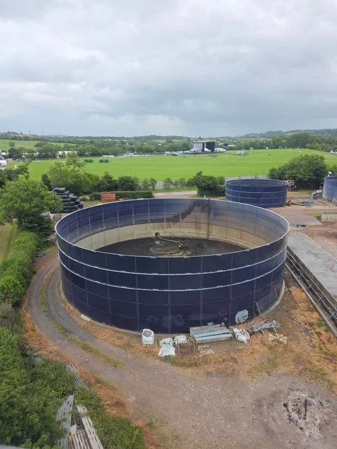
The receiving train itself is five stages: fine bar screen and grit removal; anaerobic selectors for biological phosphorus removal; an oxidation ditch that mixes wastewater with bacteria and air; a final clarifier that settles the biomass; and UV disinfection before discharge to the Mississippi River (cityoflittlefalls.com, accessed 2026). Wasted solids go to one of four aerobic digesters, then to a centrifuge, then to land application as biosolids fertilizer on approved farm fields. The UV bank and the biological-P selectors are exactly the unit operations an industrial slug endangers: a low-pH or high-FOG batch disrupts nitrification in the ditch, raises TSS out of the final clarifier, and can force the plant off its NPDES permit independently of any DMR exceedance the discharger sees.
| Little Falls POTW characteristic | Value (cityoflittlefalls.com, accessed 2026) | Implication for industrial users |
|---|---|---|
| Average dry weather flow | 1.1 MGD | 5% hydraulic trigger = 55,000 gpd → SIU threshold is low for a single line |
| Average annual design flow | 1.9 MGD | Headroom above ADW; wet-weather operations tighter |
| Peak hourly wet weather | 3.42 MGD | POTW has limited dilution capacity for slug events |
| Collection system | ~80 miles, 19 lift stations | Long residence time amplifies slug arrival profiles |
| Biological nutrient removal | Anaerobic selectors + oxidation ditch | Industrial metals/P loads can disrupt selectors |
| Disinfection | UV | UV transmittance drops sharply on FOG and TSS upsets |
| Biosolids end use | Land application on approved fields | RCRA/CWA §405 metals limits are back-propagated to IU loads |
The operational takeaway is that the on-site pretreatment train has to be sized against what the receiving plant is trying to protect — the oxidation ditch biology, the UV transmittance window, and the biosolids land-application program — not just against the federal categorical floor. A 2026 upgrade scope that ignores the biosolids back-propagation will look fine on the discharge DMR and still trigger a Clean Water Act Section 405 issue when the receiving plant's biosolids fail a metals ceiling.
The Three-Layer Compliance Stack That Controls a 2026 Discharge Near Little Falls
Three independent layers of limits can govern a single discharge from a transportation-equipment plant in Morrison County, and the most stringent applicable layer is the one that controls. The 2026 stack is, in inspector order: general and specific prohibitions under 40 CFR 403.5(a) and 403.5(b), categorical pretreatment standards under 40 CFR Parts 419/433/444, and site-specific local limits developed by the receiving POTW under 40 CFR 403.5(c) (per EPA, 2026). Skipping a layer is the most common reason an industrial user fails compliance on a parameter it believed it had covered.
Layer 1 is qualitative. 40 CFR 403.5(a) bans pass-through and interference for every industrial user, and 40 CFR 403.5(b) lists eight specific prohibitions, including pH below 5.0, closed-cup flashpoint below 140 °F (60 °C), and discharge temperature that would push the POTW above 40 °C (104 °F) (epa.gov, 2026). The verbatim definitions matter because both are enforceable independently of any numeric limit. Pass-through at 40 CFR 403.3(p) is "a discharge that exits the POTW into waters of the United States in quantities or concentrations that, alone or in conjunction with a discharge or discharges from other sources, is a cause of a violation of any requirement of the POTW's NPDES permit" (epa.gov, 2026). Interference at 40 CFR 403.3(k) is a discharge that "inhibits or disrupts the POTW, its treatment processes or operations, or its sludge processes, use, or disposal" and causes an NPDES or sewage-sludge violation (epa.gov, 2026). A slug of cutting oil or a low-pH batch from a parts washer can violate either definition even when every analyte on the DMR is in range.
Layer 2 is numeric. For a Morrison County transportation-equipment plant, the binding subparts are 40 CFR Part 433 (metal finishing) for e-coat, electrodeposition, phosphate conversion coating, and body-in-white rinsewater; 40 CFR Part 419 for petroleum-derived stamping and machining lubricants; and 40 CFR Part 444 for any foundry washwater present on-site (per EPA, 2026). EPA revises subparts on a multi-year cycle, so current values must be pulled from 40 CFR rather than recalled from memory.
Layer 3 is the local limit, written and enforced by the POTW at the collection-system connection. For a representative small-municipality Minnesota POTW, the envelope is pH 6–9, O&G 50–100 mg/L, TSS 200–300 mg/L, and total metals 1–3 mg/L per parameter (per EPA, 2026). The local limit is frequently tighter than the federal categorical floor and may tighten further on the multi-year 40 CFR 403.5(c) reevaluation cycle as the receiving plant's capacity is reassessed.
The Industrial User (IU) threshold at 40 CFR 403.3(j) is the floor every nondomestic source of process wastewater tripping a manhole crosses. The Significant Industrial User (SIU) bar is the one that brings the heavier monitoring and reporting obligations, and it triggers when any of the three 40 CFR 403.3(v) conditions fires: categorical coverage, ≥25,000 gpd process wastewater, or ≥5% of the receiving plant's ADW hydraulic or organic capacity (per EPA, 2026). For the Little Falls plant, that 5% is just 55,000 gpd — a single medium-flow line trips SIU status on hydraulic alone.
Source-by-Source Map: Where the Binding Pollutants Actually Come From in a Transportation-Equipment Plant
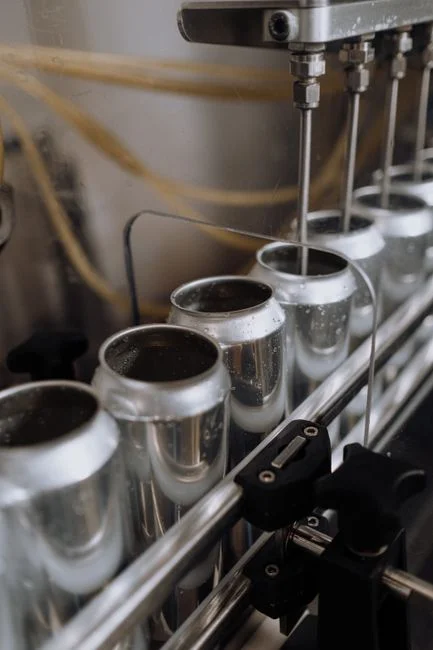
Source-stream mapping is what turns a generic pretreatment train into one that hits the binding parameter. Six streams dominate the wastewater envelope at a transportation-equipment plant in the Little Falls area, and each points to a different controlling unit operation. The first column is the engineering input, the second is the binding number, and the third is the subpart or prohibition that controls it.
| Source stream | Binding pollutant(s) & typical range | Controlling authority |
|---|---|---|
| Stamping and machining lubricants | O&G 500–5,000 mg/L; TSS 500–3,000 mg/L | 40 CFR Part 419; local O&G cap (per EPA, 2026) |
| Phosphate conversion rinsewater (BIW) | Total P 20–80 mg/L; dissolved Fe/Zn 10–100 mg/L | 40 CFR Part 433; local metals and P (per EPA, 2026) |
| E-coat / electrodeposition rinsewater | Dissolved Ni, Zn; TDS 1,000–5,000 mg/L; metals 5–50 mg/L each; anionic paint solids | 40 CFR Part 433; local metals cap (per EPA, 2026) |
| Coolant blowdown and parts-washer streams | TSS 200–1,500 mg/L with biological load | Local BOD/COD cap; no federal categorical (per EPA, 2026) |
| Batch and slug streams (acid/alkaline cleaning, spill, floor wash) | pH 4–11 swings; high instantaneous TSS | 40 CFR 403.5(b); local pH/TSS (per EPA, 2026) |
| Foundry washwater (where present) | Total metals; suspended casting sand | 40 CFR Part 444; local metals and TSS (per EPA, 2026) |
The envelopes are too wide to allow these streams to be treated as a single mixed flow, and that is the most common scoping error. A stamping and machining coolant that is 3,000 mg/L O&G cannot be sent to a metals-precipitation lamella clarifier without first breaking the emulsion and floating the FOG; conversely, a body-in-white rinsewater carrying 50 mg/L dissolved nickel cannot be handled by a DAF system for transportation-equipment FOG and TSS removal alone, because the dissolved metal fraction passes straight through the float. Each stream points to a different unit operation, and combining them upstream of treatment is what drives both capex and compliance risk.
For metals-heavy streams, an online analyzer is often the difference between a tight loop and a violation: the 2026 buyer's guide to zinc online monitoring covers the sensor and reagentless options now reaching the market. For an Indiana-side comparison of the same source-stream logic at a different small-municipality POTW, see the analogous 2026 pretreatment guide for an Indiana small-municipality POTW.
The 2026 Treatment Train That Hits Each Layer in Practice
Five unit operations, in roughly this order, handle the vast majority of transportation-equipment streams that go to a small-municipality POTW. Not every plant needs all five — the right subset is a function of the controlling pollutant identified in the source-stream map. The table below pairs each stage with the parameter it is responsible for moving and the citation that anchors the sizing.
| Stage | Unit operation | Parameter / target | Engineering spec |
|---|---|---|---|
| 1 | Equalization basin with rotary bar screen | Flow and pH damping; pass-through prevention | Sized to peak instantaneous load, not average flow (HydropureWater, 2026) |
| 2 | PLC-controlled chemical dosing + emulsion breaking | pH 6–9; conditioned O&G for DAF | |
| 3 | DAF system for transportation-equipment FOG and TSS removal | Free and emulsified FOG; bulk TSS | 4–300 m³/h across 13 standard models; micro-bubble skimming (HydropureWater, 2026) |
| 4 | Lamella clarifier for metals precipitation | Dissolved metals to 1–3 mg/L; residual TSS | 20–40 m/h surface loading; up to 30% chemical savings vs conventional (HydropureWater, 2026) |
| 5 | MBR for biological polishing | BOD/COD cap; reuse-quality effluent | PVDF 0.1 μm; ~60% smaller footprint than CAS (HydropureWater, 2026) |
| Back end | Plate-and-frame filter press for metals-bearing sludge | Cake disposal; RCRA / CWA §405 framing | Plate and frame; metals-bearing cake (HydropureWater, 2026) |
Stage 1 is the lowest-cost insurance against pass-through events and the most common root cause of failed compliance when it is undersized (per HydropureWater, 2026). Stage 2 brings strong acid and caustic batches into the 6–9 pH band required by 40 CFR 403.5(b) and conditions emulsified oils so the DAF can remove them. Stage 3 is the default first physical separation for any stream carrying free or emulsified FOG. Stage 4 cuts dissolved metals into the 1–3 mg/L local band while reducing chemical consumption up to 30% versus conventional clarifiers. Stage 5 is optional and only justified under tight BOD/COD caps or a reuse target. The back-end filter press is the disposal liability most often missed in early scoping, framed by RCRA and Clean Water Act Section 405 considerations on the biosolids side. For the physics behind Stage 3, the engineering guide on DAF working principle and microbubble physics walks through bubble-size selection and recycle ratios.
Choosing Between DAF, Lamella, and MBR: A Decision Matrix for Morrison County Plants
The honest framing is "how much headroom do you need, and for how many years" rather than "which is better." Three unit operations cover the choice space for most Morrison County plants, and the right answer is a function of the controlling pollutant and the local POTW envelope. The matrix below is the decision tool the existing top-ranking guides do not give a transportation-equipment buyer.
| Binding condition | First-choice unit operation | Trigger | Why |
|---|---|---|---|
| O&G and bulk TSS (stamping, machining, parts washer) | DAF | FOG > 200 mg/L or TSS > 300 mg/L | O&G and bulk TSS removal in one step (per HydropureWater, 2026) |
| Dissolved metals or post-precipitation TSS (paint line, phosphate line) | Chemical precipitation + lamella clarifier | Local metals cap at 1–3 mg/L per parameter | 20–40 m/h surface loading; up to 30% chemical savings (per HydropureWater, 2026) |
| Tight BOD/COD cap or reuse target | MBR | POTW cap aggressive, or reuse spec | Reuse-quality effluent; ~60% smaller footprint than CAS (per HydropureWater, 2026) |
DAF is the right first physical separation when FOG exceeds 200 mg/L or TSS is above 300 mg/L, which covers most stamping, machining, and parts-washer streams discharging from a Morrison County plant. The DAF system for transportation-equipment FOG and TSS removal handles both targets in one vessel. Lamella is the right second stage when the binding constraint is dissolved metals or post-precipitation TSS — the typical condition on a paint line, an e-coat tank, or a phosphate conversion line. MBR is justified only when the local POTW caps BOD/COD aggressively or the plant is moving toward water reuse; otherwise the activated-sludge step adds capex and opex without buying compliance headroom against the Little Falls receiving plant's oxidation ditch and UV train. Over-engineering the train by 20–30% headroom is normal practice because 40 CFR 403.5(c) reevaluation cycles tighten local limits over time (per EPA, 2026).
The Paperwork That Determines Whether the Inspection Closes Clean
Compliance is won or lost in the documents the POTW and EPA inspector actually read, not in the chemistry report alone. Four obligations cover most of the SIU compliance surface, and the one most often missing is the slug load control plan — the document most often cited when enforcement actions are filed against transportation-equipment plants.
The baseline monitoring report (BMR) is required at categorical standard promulgation or at new-discharge startup, and it establishes the pollutant envelope every later compliance report measures against (per EPA, 2026). For an existing plant, the BMR is already on file; for a new line, it is the first deliverable. 90-day compliance reports run on a defined schedule and sit alongside the written control mechanism the POTW issues; together they govern routine POTW inspections and sampling under 40 CFR 403.12 (per EPA, 2026).
The slug load control plan under 40 CFR 403.8(f) is the document most often missing in enforcement actions (per EPA, 2026). It combines equalization capacity, flow and pH monitoring, and written batch-release procedures. A slug of cutting oil or a low-pH batch from a parts washer that reaches the collection system without a written control plan is a standalone violation, independent of any numeric exceedance. Finally, EPA enforces pretreatment whether or not the receiving POTW runs an approved program — a point the agency makes explicit in its 2026 pretreatment guidance — so the obligation does not depend on local program capacity in Morrison County (per EPA, 2026). MPCA's industrial pretreatment program sits on top of the federal floor for any Morrison County SIU, and it is MPCA's review cycle that drove the Little Falls plant's 2021 renovation.
Frequently Asked Questions
What does SIU status mean for a stamping-only plant near Little Falls?
A stamping plant with no paint line and no e-coat tank is not categorically regulated, so it crosses the SIU threshold only when daily process flow hits 25,000 gpd or its mass loading reaches 5% of the Little Falls plant's 1.1 MGD ADW capacity — about 55,000 gpd of process wastewater (per EPA, 2026). Once tripped, the plant owes a BMR, 90-day compliance reports, a written control mechanism, routine 40 CFR 403.12 inspections, and a 40 CFR 403.8(f) slug load control plan.
What local limit envelope should a transportation-equipment plant expect from the Little Falls POTW?
For a representative small-municipality Minnesota POTW, the envelope is pH 6–9, O&G 50–100 mg/L, TSS 200–300 mg/L, and total metals 1–3 mg/L per parameter (per EPA, 2026). Confirm against the plant's actual control mechanism before scoping equipment, because the local limit is frequently the binding constraint and may tighten on the next 40 CFR 403.5(c) reevaluation.
Which unit operation should be specified first when FOG is the dominant parameter?
A DAF system for transportation-equipment FOG and TSS removal is the first physical separation when FOG exceeds 200 mg/L or TSS exceeds 300 mg/L, with sizing across 4–300 m³/h on 13 standard models (per HydropureWater, 2026). A DAF-plus-lamella train is the lower-capex baseline for FOG, TSS, and dissolved metals; MBR is added only when the local POTW caps BOD/COD aggressively or a reuse target exists.
What does the 40 CFR 403.8(f) slug load control plan have to include?
The plan must combine equalization capacity sized to peak instantaneous load, continuous flow and pH monitoring, and written batch-release procedures that define what a slug is and how it is contained before discharge (per EPA, 2026). A cutting-oil or low-pH slug that reaches the collection system without this written plan in place is a standalone violation, independent of any numeric exceedance on the DMR.