
What 2026 Pretreatment Limits Actually Apply to a Halls, TN Petroleum Plant
Petroleum plants near Halls, Tennessee that discharge to a publicly owned treatment works (POTW) operate under a two-layer compliance ceiling: federal categorical standards under 40 CFR Part 419 (Petroleum Refining Point Source Category) and the local sewer-use ordinance adopted by the receiving municipality. 40 CFR Part 419 sets subpart-specific daily maximum and monthly average limits for a defined list of pollutants — oil and grease, total suspended solids, phenols, chromium, ammonia, and sulfide among them — and applies whether or not the receiving POTW runs an EPA-approved pretreatment program (per EPA's 2024 guidance on pretreatment standards and requirements, last reviewed 2025-09). Bulk storage terminals and asphalt batch plants typically do not perform the full refining unit operations that trigger every subpart, but desalter brine contact, tank draw, and contaminated stormwater still pull them into categorical compliance once any listed wastewater stream is routed to the sewer.
The eight specific prohibitions at 40 CFR 403.5(b) are the second compliance layer and they apply to every industrial user regardless of categorical status. As restated on EPA's pretreatment program page (last updated 2025-09), the prohibitions cover: (1) closed-cup flashpoint below 140°F (60°C) per 40 CFR 261.21; (2) pH below 5.0 (corrosive structural damage); (3) solid or viscous pollutants causing obstruction; (4) slug loads discharged at flow rates or concentrations that cause interference; (5) heat that pushes the POTW treatment plant above 40°C (104°F); (6) petroleum oil, nonbiodegradable cutting oil, or mineral oil origin products at amounts causing pass through or interference; (7) pollutants that release toxic gases, vapors, or fumes; and (8) trucked or hauled pollutants except at POTW-designated points.
Tennessee POTWs typically translate these federal floors into numeric local limits that match a widely-used model ordinance. The Moores Hill, IN §52.29 prohibited discharges list (passed 2008, amended 2022) is a useful proxy: 25 mg/L cap on petroleum oil, pH between 5.5 and 9.5, temperature ceiling of 150°F (65°C) at the point of discharge, and explicit bans on slug loads, floatable oils, and hauled waste. Where the federal floor and the local ceiling differ, the engineer designs to the more stringent number.
Pass through (40 CFR 403.3(p)) and interference (40 CFR 403.3(k)) are the legal hooks the POTW uses when enforcement escalates. Pass through means the pollutant exits the POTW in violation of the receiving POTW's NPDES permit; interference means the discharge disrupts the POTW's treatment processes, sludge handling, or worker safety. For petroleum facilities, oil and grease is the dominant pass-through vector because emulsified oil survives primary clarification and rides out with the effluent. Tennessee's small rural POTWs often have only primary or trickling-filter biological treatment, so even 50-75 mg/L oil in the discharge can produce visible sheen on the receiving stream and trigger a state agency notice of violation. A useful field reference for engineers designing similar systems in adjacent jurisdictions is the petroleum pretreatment compliance playbook for Demopolis, AL, which covers an analogous small-municipal discharge scenario.
Wastewater Streams a Petroleum Site Has to Pretreat
Source control starts with a complete inventory. A Halls-area terminal or small refinery typically generates six distinct petroleum-contact streams, and each one has a different temperature, oil speciation, and flow profile that determines how it has to be handled before the main treatment train.
| Stream | Temperature | Oil & Grease (typical) | Key Characteristic | Pre-DAF Treatment |
|---|---|---|---|---|
| Desalter brine / produced water | 180-220°F | 100-1,000 mg/L (emulsified) | High TDS, sulfides from crude | Cool, chemical demulsifier, sulfide oxidation |
| API separator skimmings | Ambient to 120°F | Recovered free oil phase | Recoverable resource, not waste | Routed to slop oil tank, not forward |
| Tank draw and bottoms | Ambient | Variable, often >5,000 mg/L slug | Intermittent batch discharge | Equalization, slug-load monitoring |
| Stormwater contact water | Ambient | 10-200 mg/L (sheen) | High episodic volume | Diversion or dedicated DAF treatment |
| Boiler blowdown / cooling tower bleed | 100-180°F | <10 mg/L | High TDS, high temperature | Cool to <104°F, pH adjust |
| Equipment wash / spent caustic | Ambient to 140°F | 50-500 mg/L (saponified) | pH >12, sulfides | Neutralize, oxidize, then DAF |
Desalter brine and produced water arrive hot (180-220°F) and heavily emulsified, often carrying 100-1,000 mg/L oil and grease along with high total dissolved solids (TDS) and dissolved sulfides from the crude. Without cooling and chemical demulsification, this stream will overwhelm any DAF unit and strip dissolved sulfides into the collection system as H2S. Tank draw and tank bottoms behave differently — they discharge intermittently, often in batches of 5,000 mg/L oil or higher, and they are the single most common trigger for slug-load violations under 40 CFR 403.5(b)(4).
Stormwater contact water from tank-farm secondary containment is episodic but high-volume and carries visible sheen; many sites divert it through a dedicated oil-water separator during the first 30 minutes of a rain event before forwarding to the main treatment train. Boiler blowdown and cooling tower bleed run low in oil but high in temperature and dissolved solids, so they need a cooling step and pH adjustment. Spent caustic from sulfidic-crude treatment is the most aggressive stream in the inventory: pH above 12, sulfide-laden, and capable of releasing H2S the moment it is neutralized. Every caustic stream must be oxidized (typically with sodium hypochlorite or hydrogen peroxide) and brought to a pH below 9 before it enters the equalization basin, both to protect downstream equipment and to keep the collection system safe for POTW workers.
The Pretreatment Train Most Halls-Area Plants Run in 2026
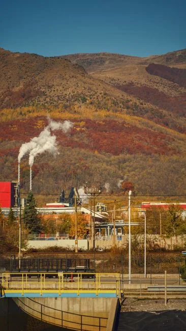
The unit-operation sequence that reliably hits 25 mg/L oil and grease, pH 5.5-9.5, flashpoint above 140°F, and discharge temperature below 104°F at the POTW headworks is equalization → grit/screening → DAF → pH/temperature trim → flow/load equalization → control manhole. Each stage ties to a specific clause in 40 CFR 403.5(b), so the design intent is documented in the P&ID narrative as well as the equipment list.
| Unit Operation | Design Parameter | Compliance Driver |
|---|---|---|
| Equalization basin | 24-48 h HRT, mechanical mixing, air sparging | 40 CFR 403.5(b)(4) slug-load prohibition |
| Rotary bar screen | 2-6 mm aperture, flows up to 300 m³/h | 40 CFR 403.5(b)(3) solids/viscous obstruction |
| DAF | 15-25 m/h surface loading, 4-6 bar saturator | 40 CFR 403.5(b)(6) oil pass-through |
| pH/temperature trim | PID loop, quench to <40°C | 40 CFR 403.5(b)(2) and (b)(5) |
| Discharge surge basin | Level-controlled, continuous outflow | 40 CFR 403.5(b)(4) and (b)(7) |
| Control manhole | Property line, 24/7 access, sampler | 40 CFR 403 + local §52.29(4) |
The equalization basin is the buffer that lets a downstream DAF run at steady design flow. 24 to 48 hours of hydraulic retention time, mechanical mixing to keep solids in suspension, and air sparging to strip dissolved sulfides and keep the basin aerobic are standard. For a 50 m³/h average discharge, a 1,200-2,400 m³ basin is typical. The basin's primary regulatory job is to absorb the slug events — tank draws, batch cleanouts, stormwater surges — that would otherwise arrive at the POTW as a single high-strength pulse and violate 40 CFR 403.5(b)(4).
From equalization, flow passes through a rotary bar screen headworks with 2-6 mm aperture to drop out rags, debris, and large solids before they reach the DAF pump nozzles. The DAF is the workhorse: an industrial DAF system with 10-20% recycle pressurized at 4-6 bar, surface loading 15-25 m/h, and air-to-solids ratio tuned to the oil load. In a properly designed DAF, micro-bubbles of 10-50 micron attach to oil droplets and float them to the surface, where a slow-moving skimmer (0.5-1.0 m/min) drags the oil phase into a sludge hopper. The 25 mg/L oil and grease number is what this stage is sized to deliver.
pH and temperature trim sits between the DAF and the discharge surge basin. A PLC-controlled chemical dosing skid feeds sodium hydroxide or sulfuric acid on a PID loop to hold pH between 6.5 and 8.5 for biological compatibility downstream; a plate heat exchanger or quench basin drops the stream to below 40°C (104°F) before it reaches the POTW headworks. A final surge basin with level control smooths flow to the control manhole, and an inline oil-in-water probe plus total oil analyzer (where installed) provides real-time compliance documentation the POTW can audit on demand.
DAF Design Parameters That Actually Hit 25 mg/L
The 25 mg/L oil and grease number is not a result of DAF alone — it is the combined effect of surface loading, recycle ratio, saturator pressure, and chemistry. A defensible DAF specification for a Halls-area terminal covers each of these explicitly so the vendor bid is apples-to-apples.
| Parameter | Design Range | Selection Logic |
|---|---|---|
| Surface hydraulic loading | 15-25 m/h (oily wastewater); 10-15 m/h (high TSS or heavy emulsion) | Lower for tighter oil targets or higher influent TSS |
| Recycle ratio | 10-20% of forward flow | Higher recycle improves bubble density; trades against pumping energy |
| Saturator pressure | 4-6 bar | Higher pressure → smaller, denser bubbles; diminishing returns above 6 bar |
| Air-to-solids ratio | 0.02-0.05 kg air / kg SS | Oil-laden streams need higher ratio to lift emulsified oil |
| Anionic polyacrylamide dose | 1-5 mg/L | Destabilizes oil emulsion; dose-jartested per batch |
| Coagulant dose (alum, PAC, or ferric chloride) | 50-150 mg/L upstream of polymer | Used when influent oil is heavily emulsified |
| Skimmer speed / beach angle | 0.5-1.0 m/min; 45-60° | Avoids re-entraining floated oil into the clarified stream |
| Effluent polishing | 50-100 micron media filter | Targets oil & grease <15 mg/L for tight local limits |
For a 50 m³/h terminal, the DAF unit itself is typically a small-to-mid frame size. Standard packaged industrial DAF system offerings run from 4 m³/h to 300 m³/h across roughly 13 frame sizes, and a Halls-area terminal or small refinery commonly lands in the DAF-5 to DAF-20 range based on HydropureWater bid history. The unit-selection logic for DAF vs. gravity clarifier is laid out in the DAF vs. gravity clarifier for petroleum wastewater guide; in short, DAF wins on footprint and on oil-removal efficiency for free and emulsified oil, while a clarifier only makes sense when the stream is already low in oil and the goal is TSS settling.
Chemistry is half the job. Anionic polyacrylamide at 1-5 mg/L provides the floc structure that captures oil droplets; the dose is jar-tested per batch because emulsion stability varies with crude source. When influent oil is heavily emulsified — a 200-500 mg/L feed from a desalter upset, for example — a coagulant (alum at 50-150 mg/L, PAC, or ferric chloride) is dosed upstream of the polymer to neutralize the surface charge. Skimmer speed and beach angle are small but important: a beach set too shallow or a skimmer running too fast re-entrains floated oil and silently pushes effluent oil and grease from 20 mg/L back to 40-50 mg/L. A 50-100 micron multimedia polish filter downstream of the DAF is the right answer when the local POTW cap is 15 mg/L or tighter (per HydropureWater field data, 2026).
Monitoring, Sampling, and the Control Manhole
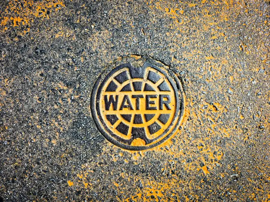
Equipment alone does not satisfy the regulator. The control manhole is the legal sampling point: it sits at the property line, is accessible 24/7, complies with OSHA 1910.146 confined-space entry rules, and is where the POTW inspector pulls the compliance sample. The §52.29(4) language used in most Tennessee-model ordinances requires a "suitable control manhole together with such necessary meters and other appurtenances in the building sewer to facilitate observation, sampling and measurement of the wastes." The manhole typically houses a 24-hour refrigerated composite autosampler, a flow meter with totalizer, and a dedicated pH/temperature probe in the flow stream.
Sampling protocol is the part the engineer documents but the lab technician executes. Minimum baseline: 24-hour flow-proportional composite for oil and grease, four grab samples per shift for pH and temperature, and a closed-cup flashpoint test per 40 CFR 261.21 on any stream with potential flammability. Oil and grease is analyzed by EPA Method 1664 (HEM, silica-gel treated); the HEM-SGT variant is the standard for petroleum-bearing matrices. Reporting frequency is monthly self-monitoring for oil and grease, pH, temperature, and flow; a full categorical standard scan under 40 CFR 419 (subpart-dependent pollutant list) is typically quarterly or semi-annual, per the discharge permit.
The slug control plan is the written procedure that defends the facility against a 40 CFR 403.5(b)(4) violation. It documents tank-draw sequencing, batch-discharge volume limits, and the high-level setpoints at which the operator must shut down a transfer and call the EHS manager. Surcharge exposure is the financial pressure that keeps the slug plan honest. POTWs typically assess surcharges for excessive BOD, TSS, oil and grease, and flow per §52.29(2)(a)(5); for a 50 m³/h discharger operating at 80 mg/L oil and grease against a 25 mg/L cap, surcharge exposure on oil alone routinely exceeds $40,000-$80,000 per year (HydropureWater field data, 2026, mid-size southern POTW tariff). Records retention is three years minimum, with chain-of-custody on every sample, every calibration, and every slug-event log entry.
Frequently Asked Questions
What oil and grease number must a Halls-area petroleum plant hit before sewer discharge?
25 mg/L total petroleum oil is the typical POTW cap, mirroring the model ordinance language used across Tennessee. Some local limits run tighter (15 mg/L) where the receiving POTW has limited oil-handling capacity; the engineer designs to the more stringent of the two. Oil and grease is measured by EPA Method 1664 (HEM, SGT-treated) on a 24-hour flow-proportional composite.
Is DAF alone enough to meet 40 CFR 419 categorical limits?
DAF handles the oil and grease and TSS sides of the categorical standard but does not address pH, temperature, or slug control on its own. The defensible 2026 train pairs DAF with equalization upstream and pH/temperature trim downstream; a control manhole at the property line is the compliance evidence the POTW actually audits.
How is flashpoint verified before discharge?
Closed-cup flashpoint is tested per 40 CFR 261.21 on a representative sample of any stream with potential flammability — typically desalter brine, light-product tank draw, and any stream exiting a process area at elevated temperature. Streams measuring below 140°F (60°C) must be segregated to a slop tank and not routed forward; a 10°F safety margin (150°F operating threshold) is standard practice.
What does a packaged DAF pretreatment skid cost a small terminal in 2026?
Installed cost for a packaged DAF with chemical dosing, control panel, and skimmer runs $80,000-$250,000 for flows in the 10-50 m³/h range typical of a Halls-area terminal, per HydropureWater 2026 bid history. Add another 30-50% for the equalization basin, control manhole, and commissioning if those are not already in place.
How are slug loads prevented at a petroleum facility?
Slug prevention rests on three layers: an equalization basin sized to absorb the largest credible batch (24-48 h HRT is standard), level-control and shutoff setpoints on every transfer pump, and a written slug control plan filed with the POTW per 40 CFR 403.5(b)(4). The plan names the responsible operator, documents the maximum batch volume, and lists the alarm setpoints that trigger a transfer shutdown.