Why Power Plants Are Re-Evaluating Nanofiltration in 2026
Cooling tower cycles of concentration in 2026 are routinely pushed past 6–8× to cut freshwater draw, which forces calcium, sulfate, and silica past their saturation limits and inflates blowdown volume. A 500 MW combined-cycle plant cycling at 7× typically blows down 200–400 m³/h of warm, high-TDS water that carries 600–1200 mg/L Ca²⁺, 1500–3000 mg/L SO₄²⁻, and 80–200 mg/L SiO₂. FGD wastewater presents additional challenges: chloride at 5,000–15,000 mg/L, sulfate at 2,000–8,000 mg/L, boron at 5–50 mg/L, selenium at 0.5–5 mg/L, plus trace mercury and arsenic (per EPA 40 CFR 423 ELG baselines). The 2024 ELG revisions tightened limits on FGD total dissolved solids and trace metals, leaving many plants to evaluate zero liquid discharge (ZLD) feasibility. NF serves as a middle option between UF and RO; it runs at half the pressure of brackish RO and selectively rejects the divalent ions that drive blowdown, giving utilities a 60–85% recovery reuse loop without the energy bill of full desalination. With 40–60% of U.S. power plants operating in water-stressed basins (per 2025 USGS water-use reporting), the pressure to reuse blowdown and FGD purge is high. These operational constraints drive the need for efficient membrane separation.
How Nanofiltration Membranes Actually Work
NF is defined by a pore size of 1–10 nm and a molecular weight cut-off (MWCO) of 100–2000 Da, placing it strictly between ultrafiltration and reverse osmosis (per the Springer 2025 NF review, S4). Three coupled mechanisms drive selectivity: size sieving (steric hindrance), Donnan exclusion (electrostatic repulsion of co-ions by the charged membrane), and dielectric exclusion (the difference in dielectric constant between bulk water and the confined pore environment) (S4). These are captured in the DSPM-DE transport model—Donnan-steric pore model with dielectric exclusion—which uses the extended Nernst-Planck equation to predict solute flux as a function of diffusion, convection, and electromigration (S4). Most commercial NF elements are polyamide thin-film composite (TFC) membranes formed by interfacial polymerization of piperazine and trimesoyl chloride on a polysulfone or polyethersulfone support (S4). Operating pressure runs 4–30 bar depending on feed TDS and recovery target; on power-plant feedwater, 4–15 bar is the realistic band (S4). The charged surface in aqueous solution gives NF its signature selectivity: divalent ions (Ca²⁺, Mg²⁺, SO₄²⁻) face strong electrostatic repulsion and are rejected at 85–95% for sulfate and 60–80% for hardness, while monovalent ions (Na⁺, Cl⁻) pass at 20–40%. Permeate flux on industrial feedwater typically falls in a 10–50 LMH band, and selectivity shifts with feed TDS, temperature (flux roughly doubles per 25 °C rise in the operating window), and recovery. The trade-off is structural: pushing recovery above 85% concentrates sulfate and silica past their scaling thresholds and collapses flux.
Power Plant Wastewater Streams Where NF Fits
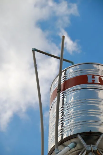
Mapping NF to a power-plant water balance identifies four specific, viable streams.
- Cooling tower blowdown: target solutes are Ca²⁺, Mg²⁺, SO₄²⁻, and SiO₂. NF delivers 60–80% hardness rejection and 85–95% sulfate rejection at 60–85% recovery—useful for sending permeate back to the tower as makeup after a polishing step.
- FGD wastewater: high TDS (10,000–35,000 mg/L), Cl⁻, SO₄²⁻, boron, selenium, and trace heavy metals. NF acts as a softening/desalination pre-stage ahead of an industrial RO polish stage after NF or a ZLD crystallizer; it drops divalent load so the downstream RO runs at higher recovery.
- Boiler makeup pretreatment: NF removes hardness and organics to protect downstream IX or RO, cutting ion-exchange regeneration frequency by 40–60% in published retrofits.
- Ash transport water and metal-cleaning waste: NF handles suspended fines, heavy metals (Fe, Cu, Ni), and high-COD streams where UF alone is insufficient—the MWCO window catches the humic and fulvic fraction that fouls RO.
| Stream | Key Target Contaminants | Typical NF Rejection | System Role |
|---|---|---|---|
| Cooling tower blowdown | Ca²⁺, Mg²⁺, SO₄²⁻, SiO₂ | 60–80% hardness; 85–95% sulfate; 30–60% silica | Recycle to tower makeup |
| FGD wastewater | Cl⁻, SO₄²⁻, B, Se, Hg, As | 80–95% divalent; 30–60% boron (pH-dependent) | Pre-stage to RO or ZLD |
| Boiler makeup pretreatment | Hardness, TOC, color | 60–90% organics; 60–80% hardness | Guard RO/IX polishers |
| Ash transport / metal cleaning | Suspended fines, Fe, Cu, Ni, COD | 90%+ TSS; 70–95% heavy metals | Reuse or safe discharge |
Use a well-specified multi-media filter for NF pretreatment ahead of the membrane skid to drop silt density index below 5. Proper pretreatment ensures membrane longevity and consistent flux rates.
NF vs RO vs Ion Exchange vs Lime Softening: Honest Trade-Offs
The decision involves balancing NF with other common technologies to meet specific plant metrics.
| Parameter | NF | Brackish RO | Ion Exchange (Na-cycle) | Lime Softening |
|---|---|---|---|---|
| Operating pressure | 4–15 bar | 10–30 bar | Atmospheric | Atmospheric |
| Specific energy (kWh/m³) | 0.3–0.8 | 0.7–2.5 | 0.1–0.3 (excl. regen) | 0.05–0.15 |
| Total ion rejection | 20–90% (selective) | 95–99.5% | Hardness only | 60–80% hardness; poor for SiO₂ |
| Recovery | 60–85% | 70–85% | 95%+ (rinse dependent) | Near 100% |
| Brine/concentrate volume | Low (15–40% of feed) | Moderate (15–30%) | Regen wastewater | Sludge (CaCO₃, Mg(OH)₂) |
| Footprint | Compact (skidded) | Compact (skidded) | Large (vessels + brine tanks) | Very large (clarifiers, sludge handling) |
| Membrane/resin life | 3–7 years | 3–5 years | 5–10 years | N/A (media replacement) |
| Best fit on power-plant water | Blowdown reuse, FGD pre-RO, makeup pretreatment | HP boiler feed, ZLD brine minimization | Final hardness polish, condensate | Bulk Ca/Mg removal, silica partial |
NF occupies a specific economic slot: roughly half the energy of brackish RO at matched divalent removal (S4), less concentrate than RO, no acid/caustic regen waste, and a smaller footprint than lime softening. NF is not a ZLD replacement on its own, and boron rejection drops to 30–60% unless pH is raised above 9.5. Lime softening remains cheaper in CAPEX but generates 0.5–2.0 kg dry sludge per m³ treated and does not touch chloride or boron. Ion exchange is appropriate for final polishing to <1 µS/cm conductivity on condensate, but resin regeneration waste and sodium-cycle cost push plants toward NF pretreatment first. These trade-offs define the integration strategy for most modern facilities.
Designing a Nanofiltration Train: 2026 Process Flow
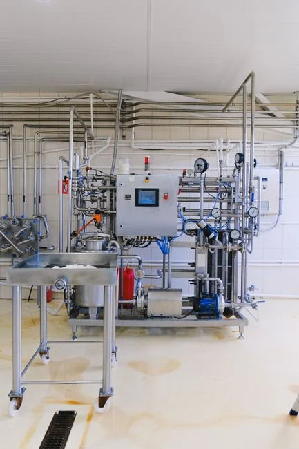
A defensible 2026 NF train on a power-plant reuse loop runs five stages:
- Intake / headworks: install a rotary bar screen at headworks with 6–10 mm openings to protect downstream pumps from rags, scale chips, and ash carryover.
- Equalization and clarification: an equalization basin (4–8 h retention) followed by a DAF clarifier upstream of NF or a lamella clarifier to drop TSS, oil, and FOG below 30 mg/L—critical because free oil fouls TFC polyamide within hours.
- Media filtration: a multi-media filter for NF pretreatment (anthracite/sand/garnet) targeting SDI₁₅ < 5 and turbidity < 1 NTU before the NF skids.
- NF skid: 4–15 bar operation, two-pass or two-stage array depending on recovery target. Include an antiscalant and CIP chemical dosing skid, a flush tank, and a CIP loop (hot caustic at pH 11–12 followed by acid wash at pH 2–3 is typical).
- Polish / reuse: if permeate feeds an HP boiler, send it to an industrial RO polish stage after NF followed by mixed-bed IX; if permeate returns to the cooling tower, NF permeate plus a side-stream blowdown bleed is often sufficient.
Recovery is set by the saturation index of calcium sulfate and silica in the concentrate. For a 75% recovery design point on cooling tower blowdown at 2,500 mg/L SO₄²⁻, the concentrate will sit near 10,000 mg/L SO₄²⁻; antiscalant dose and pH control must be sized for that endpoint.
Fouling, Pretreatment, and Operating Risks
NF failure on power-plant feedwater is almost always fouling, not membrane defect (S4). Four fouling modes dominate: silica scaling above 150–180 mg/L SiO₂ in the concentrate; iron fouling from upstream corrosion (Fe > 0.1 mg/L is enough to collapse flux over weeks); calcium sulfate and calcium carbonate scaling; and biological growth on the membrane surface when feed is warm (30–40 °C) and organic-rich. Standard feed targets are SDI₁₅ < 5, turbidity < 1 NTU, Fe < 0.1 mg/L, and free chlorine < 0.1 mg/L (polyamide TFC tolerance). Antiscalant selection must match the concentrate chemistry—sulfate-scale inhibitors are not interchangeable with silica dispersants, and overdosing silica dispersant can foul RO polishers downstream. CIP frequency of 1–4 weeks is realistic on power-plant feedwater; budget two cleaning chemistries (caustic + EDTA for organic/biologic, acid for scale) and hold 10–15% of installed membrane area as replacement inventory. A more detailed pretreatment spec is in the 2026 RO design criteria reference—most of the upstream rules apply to NF as well, with relaxed SDI targets and lower pressure ratings. For multi-site planning, see the industrial park wastewater planning guide. Proactive maintenance mitigates these risks effectively.
Frequently Asked Questions
What pore size and MWCO define a nanofiltration membrane for power plant wastewater?
NF membranes are defined by 1–10 nm pore size and
Frequently Asked Questions
What contaminants does nanofiltration remove from power plant cooling tower blowdown?
Nanofiltration (NF) membranes are highly effective at rejecting divalent and multivalent ions such as calcium (Ca2+), magnesium (Mg2+), and sulfates (SO42-), which are primary contributors to scaling in cooling systems. The technology typically achieves 80% to 95% rejection of these hardness ions while allowing a higher percentage of monovalent ions like sodium and chloride to pass through the membrane.
How does nanofiltration compare to reverse osmosis for power plant wastewater reuse?
Nanofiltration operates at lower pressures than reverse osmosis (RO), often resulting in 30% to 50% lower energy consumption for comparable throughput. While RO provides near-total demineralization by removing nearly all dissolved solids, NF is more selective, targeting specific multivalent ions and organic compounds with molecular weights typically between 200 and 1,000 Daltons, making it ideal for applications where selective ion removal is required without complete desalination.
What feed pressure does an NF system run at in a power plant?
In power plant wastewater applications, NF systems generally operate within a feed pressure range of 75 to 250 psi (5 to 17 bar). This is significantly lower than the 400 to 800 psi required for typical seawater or brackish water reverse osmosis systems, allowing for the use of less robust piping materials and smaller high-pressure pump configurations.
Can nanofiltration replace ion exchange for boiler makeup pretreatment?
Nanofiltration is frequently used as a primary pretreatment step to reduce the ionic load before ion exchange, but it rarely replaces ion exchange entirely for high-pressure boiler makeup requirements. By removing the bulk of hardness and dissolved organic carbon, NF significantly extends the service runs of downstream ion exchange resins and reduces the frequency of chemical regeneration cycles, though final polishing via demineralization is still necessary to reach high-purity water standards.
What is the typical recovery rate for an NF system on FGD wastewater?
For flue gas desulfurization (FGD) wastewater treatment, NF systems typically achieve recovery rates between 70% and 85%. The exact recovery is limited by the solubility limits of sparingly soluble salts like calcium sulfate (gypsum); therefore, advanced antiscalant dosing and precise monitoring of the concentration polarization factor are required to prevent membrane fouling and scaling at these high recovery levels.