

What a PAM Dosing System Is — and Why the Design Criteria Matter
A PAM dosing system is the integrated unit that stores dry or emulsion polyacrylamide flocculant, wets and dissolves it, matures the solution, holds it in a storage tank, and injects it at a controlled rate into the wastewater stream. The design is anchored by four non-negotiable criteria: (1) a polymer solution concentration of 0.1–0.5% w/w, (2) a maturation/curing time of 45–60 minutes before the solution reaches the dosing pump, (3) an active-polymer dose range of 0.5–10 mg/L into the wastewater, and (4) a PLC-controlled metering pump paced to influent flow. Any skid-mounted PLC-controlled chemical dosing system that fails on one of those four points will either under-dose (no floc) or over-dose (restabilized particles, 10–20% wasted polymer) once the process stream drifts from its commissioning baseline.
Why the four criteria matter: under-dosing leaves the suspension charge only partially neutralized, so flocs never form properly and clarifier effluent stays turbid. Over-dosing reverses the surface charge of the suspended solids, restabilizes the colloid, and pushes polymer consumption — typically the single largest variable opex line in a sludge dewatering plant — well above what a jar test would have predicted. Properly executed, jar-test commissioning alone returns a 10–20% polymer reduction at most industrial sites (per S3, 2025 dosing-optimization data). Acrylamide monomer toxicity is the other driver: commercial PAM must carry low-residual certification so discharge streams contacting potable reuse, food processing, or membrane systems stay within WHO/NSF limits, and a properly speced dosing skid is where that control starts.
Step 1 — Select the PAM Chemistry for the Wastewater
Chemistry selection precedes every downstream hardware decision, because a 0.1% change in charge density can swing the optimal dose by 2–3×. The rule is charge matching, not analogy: pick the polymer whose ionic character counteracts the surface charge of the suspended solids at process pH (per S4, 2025 wastewater-treatment application notes).
- Cationic PAM (CPAM) — positive charge. Default choice for sludge dewatering, biological treatment, and any organic-rich stream where particles carry a net negative charge (most municipal biosolids, food waste, pulp & paper primary sludge).
- Anionic PAM (APAM) — negative charge. Used in industrial and mineral wastewater where colloids are positively charged — metal-ore tailings, coal preparation, some textile dye baths.
- Non-ionic PAM (NPAM) — neutral. Reserved for high-salinity or high-organic streams where ionic polymers lose effectiveness through charge shielding (per S4).
Drive the final pick by jar test, not by analogy. The same influent can flip optimal chemistry with seasonal swings — a coal preparation plant that runs APAM in winter may need NPAM in summer when total dissolved solids climb above 5,000 mg/L. The two selection axes to track are molecular weight (higher MW = larger flocs, often lower dose) and charge density (the second axis that determines how many active sites the chain exposes) (per S3, 2025 dosage guidance). A matched pair — for example, a high-MW cationic with 30–50% charge density — usually outperforms a higher-dose mid-MW product by 15–25% on net dry-solids capture.
Step 2 — Specify the Preparation Concentration and Maturation Time
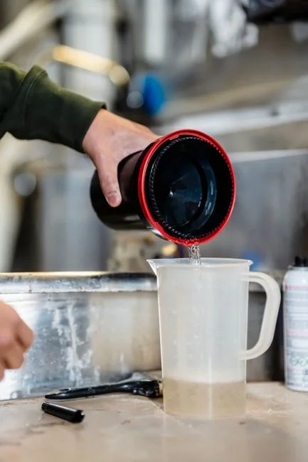
Preparation concentration and maturation time control every downstream tank volume and pump size, so they belong at the top of the datasheet, not at the bottom. Target 0.1–0.5% w/w polymer in the dissolution tank; this is the working range where the powder fully wets, the chains uncoil without crowding, and the solution stays pumpable without becoming so viscous that the metering pump loses prime (per S2 manufacturer design data, 2025).
Hold the prepared solution in the maturation/aging tank for 45–60 minutes before it reaches the dosing pump. This window is what allows the polymer chains to uncoil and present their active sites — feed the pump earlier and the dose that lands in the clarifier is functionally 20–40% lower than what the flow meter thinks it sent. Independent sources converge on the 30–60 minute range (per S4) for full activation; treat 45 minutes as the engineering floor and 60 minutes as the design target.
Two equipment details make or break prep quality. First, install a high-efficiency vortex pre-wetting device at the dry-powder inlet: dry polymer dumped straight into a stirred tank forms fish-eyes and lumps that never dissolve, and those lumps are the single most common cause of under-dosing in field service. Second, hold maturation-tank agitation at ≤150 rpm: high shear fragments the polymer chains and destroys bridging capacity, which is the dominant floc-forming mechanism for high-MW products. The rule of thumb is enough tip speed to keep solids in suspension, not enough to shear the solution (per S3 mixing guidance).
Step 3 — Calculate the Dose Rate and Pump Capacity
The dose range of 0.5–10 mg/L of active polymer is a starting envelope, not a design number — refine it with a jar test against the actual mixed liquor or process sidestream. Municipal plants typically settle in the lower half of the range; industrial wastewater with higher total suspended solids pushes toward the upper end (per S3, 2025 dosing data).
Convert that envelope into a pump capacity the engineer can write into a datasheet:
Qpump (L/h) = Qinfluent (m³/h) × dose (mg/L) ÷ (Csolution (g/L) × 1000) × safety factor
For a 100 m³/h stream, a 2 mg/L dose, and a 0.2% (2 g/L) solution, the calculation gives 100 L/h of prepared polymer solution. Across the full 0.1–0.5% concentration range and 0.5–10 mg/L dose range, the practical pump output sits between roughly 50 and 500 L/h for a 100 m³/h stream (synthesis from S2 and S3).
Specify a diaphragm or peristaltic metering pump. Peristaltic is preferred for shear-sensitive high-MW polymer and for any abrasive duty (e.g., emulsion PAM with undissolved carrier), because the fluid contacts only the tubing — no check valves, no seals to wear. Demand a minimum 10:1 turndown ratio so the pump rides diurnal flow swings and solids-load changes without re-priming or stroking against a dead-headed line. Finally, apply a 1.5–2× safety factor on the dose so the upper end of the range is reachable without pump replacement; this matches manufacturer guidance to oversize the dry-powder feeder relative to the steady-state requirement (per S2 max-dose design notes).
Step 4 — Size the Tanks for Continuous 24-Hour Operation
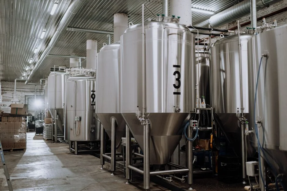
Use a three-tank train: dissolution → maturation → storage. The dissolution tank receives wetted powder and makeup water; overflow into the maturation tank starts the 45–60 minute hold; overflow into the storage tank stages the mature solution for the metering pump. Continuous 24-hour operation is the default design point — the skid makes new solution on one side while feeding the process on the other (per S2 manufacturer design data).
Tank sizing follows two simple formulas:
Vdissolution (m³) ≈ (Qpump × 60 min) ÷ 1000
Vmaturation (m³) ≈ (Qpump × 60 min) ÷ 1000 (to honor the 45–60 min hold)
Size the storage tank for at least 8 hours of average demand. That buffer is what lets the next batch be prepared and matured while the process keeps running; without it, every powder refill becomes an unscheduled shutdown. The level-control loop on an automatic skid is straightforward: dissolution overflows to maturation when full, maturation overflows to storage when full, and the storage tank supplies the metering pump until its low-level switch triggers a new batch (per S2).
One more tank belongs upstream of the dry-powder feeder: a day tank sized for ≥7 days of polymer consumption. Decoupling polymer supply from pump operations is the cheapest insurance against a missed delivery becoming a process outage, and it is standard practice on automatic skids (per S2 hopper/feeder design).
Step 5 — Specify the Control Logic, Materials, and Injection Point
Control logic is where most field failures are born or prevented. Specify a PLC or SCADA controller with four interlocks as a minimum: flow-paced dosing from the influent magnetic flow meter, tank-level interlocks on each of the three vessels, a dry-powder low-level alarm on the day tank, and a pump-fault alarm that fails the skid to a safe state on loss of stroke (per S4 control-panel description, 2025). Flow pacing alone typically cuts polymer consumption 8–15% versus fixed-rate dosing, because the pump tracks the actual hydraulic load instead of running flat-out during low-flow hours.
Wetted materials determine long-term reliability. Use HDPE, PP, or stainless 304 for tanks and piping; EPDM or Viton for seals. Avoid carbon steel (it corrodes and the iron contamination degrades PAM) and avoid copper and copper alloys (copper catalyzes polymer degradation and discolors the solution). These material choices are standard across the manufacturer datasheets (synthesis from S2 equipment specifications).
Locate the injection point upstream of the clarifier, DAF unit, or centrifuge, with a static mixer or an open-channel turbulence zone to distribute the dose across the full flow cross-section. A well-placed injection point typically improves floc growth by 20–30% over a simple tee into a pipe. When influent turbidity or color is high, always pair PAM with a coagulant — PAC, alum, or ferric chloride — to handle the colloidal fraction that PAM alone cannot bridge (per S4 and S5). Finally, require residual-acrylamide certification on every polymer grade used in potable reuse, food processing, or membrane-system applications; commercial PAM for those duties is typically specified at <0.05% residual monomer to stay within WHO drinking-water guidelines.
The same design language carries through to sludge dewatering: the upstream flocculation step is what makes the downstream device — a filter press, centrifuge, or a downstream dissolved air flotation unit — actually perform. Cross-reference the sludge dewatering system design criteria guide when sizing the dewatering device so the floc structure it sees matches the polymer dose it was designed for, and the 2026 flocculant dosing unit selection guide when ranking hardware shortlists.
PAM Dosing System Design Criteria — Quick-Reference Parameter Table
The table below is the copy-paste block for a datasheet or RFQ. Numbers are design targets, not field averages; refine the dose after commissioning jar tests.
| Design Parameter | Specification | Source / Note |
|---|---|---|
| Solution concentration (dissolution tank) | 0.1–0.5% w/w | S2, 2025 manufacturer design data |
| Maturation / curing time | 45–60 min | S2, S4 (S4 cites 30–60 min range) |
| Active-polymer dose rate | 0.5–10 mg/L into wastewater | S3, 2025 dosing guidance |
| Metering pump type | Diaphragm or peristaltic, ≥10:1 turndown | S4, 2025 application notes |
| Dose safety factor | 1.5–2× on calculated steady-state | S2 max-dose design guidance |
| Tank train | Dissolution → maturation → storage; storage ≥8 h of average demand | S2, 2025 design data |
| Day tank (dry powder) | ≥7 days of consumption | S2 hopper/feeder design |
| Maturation agitation | ≤150 rpm (low-shear) | S3 mixing guidance |
| Wetted materials | HDPE / PP / SS304; EPDM or Viton seals; no carbon steel, no copper | Synthesis from S2 equipment specs |
| Control | PLC / SCADA; flow-paced dosing; level interlocks; dry-powder low-level alarm | S4, 2025 |
| Injection point | Upstream of clarifier, DAF, or centrifuge; static mixer recommended | S4, 2025 |
| Coagulant pairing | PAC, alum, or ferric chloride when influent turbidity or color is high | S4, S5 |
| Residual acrylamide | <0.05% monomer for potable / food / membrane contact | WHO drinking-water guidance, 2025 |
| Typical saving from jar-test commissioning | 10–20% polymer reduction | S3, 2025 field data |
Frequently Asked Questions
What concentration of PAM solution should a dosing skid prepare?
Target 0.1–0.5% w/w polymer in the dissolution tank. This is the working range where the powder fully wets, the chains uncoil without crowding, and the solution stays pumpable. Above 0.5% the viscosity rises sharply and the metering pump can lose prime; below 0.1% the per-liter water demand on the storage tank grows uneconomically (per S2, 2025 manufacturer design data).
How long should PAM solution mature before it is dosed?
Hold the solution in the maturation tank for 45–60 minutes. This window is what allows the polymer chains to uncoil and present their active sites. Independent sources cite 30–60 minutes (S4); treat 45 minutes as the engineering floor and 60 minutes as the design target so the dose that reaches the clarifier matches what the flow meter is sending.
What metering pump turndown ratio is needed for a PAM dosing system?
Specify a minimum 10:1 turndown ratio. This is what lets the pump ride diurnal flow swings and solids-load changes without re-priming or stroking against a dead-headed line. Peristaltic pumps are preferred for shear-sensitive high-MW polymer and abrasive emulsion grades because the fluid contacts only the tubing (per S4, 2025 application notes).
How is residual acrylamide controlled on a PAM dosing skid?
Require low-residual certification on every polymer grade used in potable reuse, food processing, or membrane-system applications. Commercial PAM for those duties is typically specified at <0.05% residual acrylamide monomer to stay within WHO drinking-water guidelines. The dosing skid itself does not reduce residual monomer — it delivers a certified product at a controlled rate — so the certificate is a procurement-line item, not an operating parameter (per S4, 2025).