
What "Pressure Flotation System Design Criteria" Actually Means in 2026
Pressure flotation system design criteria in 2026 are six linked parameters: hydraulic surface loading of 3–10 m³/(m²·h), flotation retention time of 15–40 minutes, saturator pressure of 4–6 bar (≈0.4–0.6 MPa) with a 15–50% recycle ratio, bubble size of 30–50 µm, an air-to-solids ratio of 0.005–0.20 lb air/lb solids, and a gas-to-solids ratio validated by bench testing. These six govern sizing; everything else — skimmer type, tank material, control platform — is selection criteria, not design criteria, and it can be swapped without changing the hydraulic envelope (per Hixson 2026-02; Fylypchuk et al., Sci Rep 2026, doi:10.1038/s41598-026-39418-2).
What the top vendor pages miss is that all six numbers are coupled through the gas content G(i) delivered to the flotation chamber. Change the saturator pressure and the required recycle ratio moves. Change the recycle ratio and the bubble size distribution shifts. Change the elevation and the hydrostatic head Ph inside the gas-content equation moves all four gas-side numbers at once. A buyer who treats the six as independent picks will usually end up with a saturated pump and an undersized tank, or vice versa. The two anchor references used throughout this guide are the Hixson 2026 design criteria article (food/FOG focus, US industry data) and the Fylypchuk et al. 2026 paper in Scientific Reports (metal-hydroxide focus, gas-content equation). For a turnkey packaged unit that locks in steps 2 through 4, see a dissolved air flotation (DAF) system spec sheet as the reference for what a properly designed tank envelope looks like.
Step 1: Characterize the Influent Before Sizing Anything
Pressure flotation design fails most often because the influent characterization was wrong, not because the hydraulic math was wrong. At minimum, capture peak flow (not 24-hour average), TSS, FOG, BOD/COD, pH, temperature, and particle density on the actual waste stream (per Hixson 2026-02). For municipal and food streams this is standard; for metal-finishing and mining streams the particle density term is the one most often left out, and it is the term that drives the lower bound of the air-to-solids ratio.
Metal hydroxide flocs form a porous, low-density structure at 1010–1030 kg/m³ — close to water — which is why they float stably even with minimal gas input (Fylypchuk et al., Sci Rep 2026, doi:10.1038/s41598-026-39418-2). That structural fact is what allows industrial A/S ratios in the 0.005–0.02 lb air/lb solids range to work on metal-hydroxide streams, while FOG and protein streams need the high end of the 0.005–0.200 range because the float material is genuinely less dense and the bubble must lift a larger attached mass.
Bench-scale jar testing is mandatory because the published 0.005–0.200 lb air/lb solids range spans a factor of 40. Treatability work confirms the actual A/S, screens coagulant and flocculant chemistry, and produces the experimentally determined G/S ratio that the gas-content equation needs as an input (per Hixson 2026-02; Fylypchuk et al. 2026). For any stream where total metals exceed 500 mg/dm³ (mg/L), the treatability study should also evaluate a multistage configuration, because single-stage units lose selectivity and recovery above that threshold (Fylypchuk et al. 2026).
Step 2: Set the Hydraulic Loading and Retention Time
Two numbers define the flotation tank envelope: hydraulic surface loading rate and flotation retention time. Hydraulic surface loading rate is design flow divided by tank plan area, with a working range of 3–10 m³/(m²·h) and a typical industrial design point near 5 m³/(m²·h) (Fylypchuk et al., Sci Rep 2026, doi:10.1038/s41598-026-39418-2). Flotation retention time is tank volume divided by (influent + recycle flow), with a working range of 15–40 minutes and a typical design point near 25 minutes (Fylypchuk et al. 2026). The two together let the engineer size tank area and tank volume independently from the gas-side design.
Compared to gravity settling, pressure flotation is roughly 4–6× faster on retention time (20–30 min vs 1.5–3.0 h) and produces a noticeably drier float sludge at 88–92% moisture versus 96–98% for settled sediment (Fylypchuk et al. 2026). That sludge-moisture delta directly shrinks the downstream dewatering load — a meaningful operating cost when the float sludge feeds a filter press or centrifuge.
Tank sizing must use peak flow, not average flow. Undersized contact zones are the dominant cause of downstream TSS exceedances because surge events consume the design margin that average-flow sizing leaves in the tank (per Hixson 2026-02). Recycle flow adds to the hydraulic load and must be included in the denominator of the loading-rate calculation. The consolidated design criteria below carry both peak-flow sizing and the recycle correction in the same line.
| Criterion | Industrial range | Typical design point | Sizing formula | Source |
|---|---|---|---|---|
| Hydraulic surface loading | 3–10 m³/(m²·h) | 5 m³/(m²·h) | A = Qpeak / loading rate | Sci Rep 2026 |
| Flotation retention time | 15–40 min | 25 min | V = (Qww + Qrw) × tf | Sci Rep 2026 |
| Saturator pressure Ps | 0.4–0.6 MPa (4–6 bar) | 0.4–0.5 MPa | Set by pump curve | Hixson 2026-02 |
| Recycle ratio Rrw | 0.15–0.50 (general) / 0.5–1.0 (metal) | 0.30–0.50 | R = Qrw / Qww | Hixson 2026-02; Sci Rep 2026 |
| Bubble size db | 10–100 µm | 30–50 µm | Set by nozzle/nozzle + pressure | Hixson 2026-02 |
| A/S ratio | 0.005–0.200 lb air / lb solids | 0.01–0.05 | Bench-confirmed | Hixson 2026-02 |
| G/S ratio | Bench-confirmed | — | Eq. 29 back-calc | Sci Rep 2026 |
| Float sludge moisture | 88–92% | — | — | Sci Rep 2026 |
| Settling sludge moisture (reference) | 96–98% | — | — | Sci Rep 2026 |
Step 3: Pick the Saturator Pressure, Recycle Ratio, and Bubble Size
Saturator pressure is the single most leveraged design choice. The 4–6 bar (≈0.4–0.6 MPa, 58–87 psi) industrial range is set by Henry's Law: more pressure dissolves more air, and the dissolved-air inventory is what becomes the bubble population when the recycle stream is depressurized at the nozzle (per Hixson 2026-02). The recycle ratio Rrw = Qrw/Qww is a tuning knob, typically 15–50% on general DAF and 0.5–1.0 on metal-wastewater service (per Hixson 2026-02; Fylypchuk et al., Sci Rep 2026, doi:10.1038/s41598-026-39418-2).
The governing relationship is the gas-content equation, expressed in the form the buyer can act on (Eq. 6 from Fylypchuk et al. 2026):
G(i) = 273 · ks · kD · W(i) · (Ps − Ph) · Rrw / [0.101335 · (273 + tair) · (1 + Rrw)]
where G(i) is gas content in cm³/dm³, ks is the saturator efficiency coefficient, kD is the residence-time factor, W(i) is the maximum air solubility at the operating water temperature, Ps is saturator pressure in MPa, Ph is hydrostatic head at the mixing point, Rrw is the recycle ratio, and tair is the air temperature in °C.
The worked numbers from the paper make the leverage visible. At a saturator pressure of 0.2 MPa and Rrw = 0.5, the gas content is 6.46 cm³/dm³. Raising Ps to 0.4 MPa at the same Rrw lifts G(i) to 13.64 cm³/dm³ — a 2.1× increase, which matches the pressure-difference ratio (0.4 − 0.02) / (0.2 − 0.02) once the hydrostatic head is subtracted (Fylypchuk et al. 2026). Doubling the recycle ratio from 0.5 to 1.0 at 0.4 MPa only raises G(i) 1.5×, to 20.47 cm³/dm³ — the same 1.5× that comes from raising Ps to 0.6 MPa at Rrw = 0.5. The takeaway is that pump pressure buys more gas content per unit of recycle flow than the recycle ratio itself does.
Bubble size is set to 30–50 µm as a design target. The 10–100 µm range is what the system actually produces, but the 30–50 µm band is where particle adhesion and rise velocity are both workable (per Hixson 2026-02). For high-altitude sites, the (Ps − Ph) term in the gas-content equation is what matters, not Ps alone. At sites where atmospheric pressure is meaningfully below 101.325 kPa, the saturator setpoint must be raised to hold the same Ps − Ph differential, or the gas content delivered to the chamber will quietly drop below design (Fylypchuk et al. 2026).
| Lever | Change | Resulting G(i) at 20 °C | Multiplier | Source |
|---|---|---|---|---|
| Saturator pressure | Ps 0.2 → 0.4 MPa, Rrw = 0.5 | 6.46 → 13.64 cm³/dm³ | 2.1× | Sci Rep 2026 |
| Recycle ratio | Rrw 0.5 → 1.0, Ps = 0.4 MPa | 13.64 → 20.47 cm³/dm³ | 1.5× | Sci Rep 2026 |
| Pressure (alt. path) | Ps 0.4 → 0.6 MPa, Rrw = 0.5 | 13.64 → 20.83 cm³/dm³ | 1.5× | Sci Rep 2026 |
Step 4: Choose a Saturator Type by Saturation Efficiency (ks)
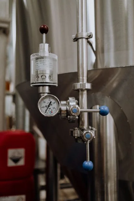
The saturator type sets the ks coefficient in the gas-content equation, and that single coefficient can move delivered gas by a factor of roughly 3× at the same pump pressure. A bubbling-type saturator — the cheapest configuration, a retention tank with diffused air — runs at ks = 0.16–0.35. A jet aeration saturator, where motive water draws gas through an ejector, runs at ks = 0.7–0.9. A two-stage saturator, which combines a venturi with a packed retention section, runs at ks = 0.8–0.95. A mass-transfer nozzle saturator — a purpose-built nozzle designed to maximize gas–liquid contact area under pressure — runs at ks = 0.95–1.0 (Fylypchuk et al., Sci Rep 2026, doi:10.1038/s41598-026-39418-2).
The residence-time factor kD overlays on top of ks. At T = 2 min in the saturator, kD = 0.7–0.8. At T = 5 min, kD = 0.8–0.9. At T > 5 min, kD = 0.9–0.95 (Fylypchuk et al. 2026). Bubbling saturators need longer residence time to compensate for low ks; mass-transfer nozzle saturators can run at short residence time because ks is already near unity. The combined effect is that a poorly selected saturator on a high-metal stream will underdeliver gas even if the pump is correctly sized — a common source of disappointing field results on retrofits where the original vendor spec was carried over to a new waste stream. For a packaged DAF unit that locks in the saturator, nozzle, and recycle pump as a matched set, see the dissolved air flotation (DAF) system reference design.
| Saturator type | ks range | Typical kD (at design T) | Effective gas delivery | Source |
|---|---|---|---|---|
| Bubbling tank | 0.16–0.35 | 0.7–0.95 (T > 5 min) | 0.11–0.33 | Sci Rep 2026 |
| Jet aeration / ejector | 0.7–0.9 | 0.8–0.9 (T = 5 min) | 0.56–0.81 | Sci Rep 2026 |
| Two-stage | 0.8–0.95 | 0.8–0.9 (T = 5 min) | 0.64–0.86 | Sci Rep 2026 |
| Mass-transfer nozzle | 0.95–1.0 | 0.7–0.8 (T = 2 min) | 0.67–0.80 | Sci Rep 2026 |
Step 5: Validate With the Air-to-Solids or Gas-to-Solids Ratio
The A/S ratio is the operating-floor check: mass of air released per mass of influent solids, with an industrial range of 0.005–0.200 lb air / lb solids (per Hixson 2026-02). It is the number operators watch day to day because it ties gas delivery to the actual solids load on the unit. It is also the parameter that bench-scale jar testing is meant to confirm, because the published range spans a factor of 40 and the right value depends on particle density, FOG fraction, and float structure.
The G/S ratio is the design-side counterpart: volume of gas delivered per mass of solids, determined experimentally on the actual waste stream (Fylypchuk et al., Sci Rep 2026, doi:10.1038/s41598-026-39418-2). It is the input to Eq. 29, which back-calculates the required gas content G(i) in the flotation chamber from a confirmed G/S:
G(i) = (G/S) · Cm / ρair
where Cm is the solids (or metal) concentration in the wastewater and ρair is air density at operating conditions. Once G(i) is known, the saturator and recycle settings from step 3 are tuned to deliver that gas content to the chamber. The two ratios are not redundant — A/S is what the operator measures on the running unit; G/S is what the design engineer uses to size the saturator system.
There is also a hard physical ceiling. For a particle to float with only one bubble attached, its density must satisfy ρp(1) < ρww · (1 + wb(av)/wp(av)) (Eq. 26, Fylypchuk et al. 2026). This bound sets the largest particle the unit can lift on a single bubble, and it is the reason very dense or coarse grit must be screened out upstream of flotation rather than expected to float.
Worked Example: 15 m³/h Metal-Containing Wastewater
A 15 m³/h metal-containing wastewater stream at 20 °C with total metals Cm = 1.0 g/dm³ (= 1.0 kg/m³) is a useful worked case because it lands inside the published envelope and exercises the gas-content equation end to end. Apply hydraulic loading of 5 m³/(m²·h) to the combined influent-plus-recycle flow, which gives a tank plan area of about 3 m². Apply flotation retention time of 25 minutes, which gives a tank volume of about 9.4 m³ once the recycle stream is included in the denominator (per Hixson 2026-02; Fylypchuk et al., Sci Rep 2026, doi:10.1038/s41598-026-39418-2).
Set the saturator at Ps = 0.4 MPa with Rrw = 0.5. With a mass-transfer nozzle saturator (ks = 0.95) and a residence-time factor of about 0.8, the gas-content equation returns G(i) ≈ 12.9 cm³/dm³ in the flotation chamber — a comfortable margin above the bench-confirmed minimum. Because Cm = 1.0 g/dm³ exceeds the 500 mg/dm³ multistage threshold, the design should call out a two-stage unit for selective metal recovery, not a single-stage unit (Fylypchuk et al. 2026).
The economic case is concrete. At 1.0 g/dm³ metal concentration and 15 m³/h throughput, a two-stage pressure flotation unit can selectively extract more than 60 t/yr of metals for recycle, with float sludge at 88–92% moisture versus 96–98% for the equivalent settled sediment (Fylypchuk et al. 2026). The lower moisture alone cuts downstream dewatering volume by roughly a factor of three, which is what makes the float sludge economically attractive to feed to a plate and frame filter press for the float sludge. For mining-stream procurement context, the comparison in this DAF vs clarifier for mining wastewater in Atmore guide lays out when flotation beats gravity on the same feed.
Sizing, Materials, and Controls That Round Out the Design
Once the six design criteria are locked, three selection decisions remain: tank geometry, material of construction, and the control loop. Rectangular tanks are the most common configuration and the easiest to integrate with chain-and-flight skimmers. Circular tanks suit high-rate retrofits where footprint is constrained. High-rate lamella configurations (inclined plates inside the tank) push the effective hydraulic loading rate toward the upper end of the 3–10 m³/(m²·h) range at the cost of more sensitive sludge handling (per Hixson 2026-02).
Material selection is driven by the corrosion profile of the waste stream. 304 or 316L stainless steel suits corrosive or food-grade service. Coated carbon steel is acceptable for less aggressive service at lower capital cost, with the trade-off being closer maintenance attention over the service life (per Hixson 2026-02). Skimmer selection ties to the float-sludge dryness target — chain-and-flight for continuous high-volume, spiral screw for food-grade, and vacuum for the driest float where downstream dewatering is sensitive to incoming moisture.
Control loops are the difference between a unit that hits design on day one and a unit that drifts off-spec by month six. The minimum set is pH, level, recycle pressure, and saturator level, all tied back to a single PLC. On mid-sized food plants, automating coagulant and flocculant dosing against flow-proportional setpoints saves $50,000–$150,000 per year in chemical OPEX because operators no longer over-dose by hand to compensate for setpoint drift (per Hixson 2026-02). For the dosing skid itself, a PLC-controlled coagulant and flocculant dosing package keeps the chemistry stage coupled to the flotation stage rather than running on independent timers. For metals and petroleum streams where the chemistry window is tighter, the comparison in DAF vs clarifier for petroleum and organic chemicals wastewater in Dickinson, US and the metals-specific discussion in DAF vs clarifier for mining/metals wastewater in Chicken, US are useful side references when the buyer is selecting between primary treatment technologies rather than sizing the DAF itself.
Frequently Asked Questions
What is the difference between A/S and G/S ratio in DAF design?
A/S ratio is mass of air released per mass of influent solids, with an industrial range of 0.005–0.200 lb air / lb solids and is the operating-floor number watched on the running unit (per Hixson 2026-02). G/S ratio is the volume of gas delivered per mass of solids, determined by bench testing on the actual waste stream, and is the design input used in Eq. 29 of Fylypchuk et al. (Sci Rep 2026) to back-calculate required gas content in the flotation chamber.
Why does saturator pressure matter more than recycle ratio?
Gas content scales with (Ps − Ph) · Rrw in the gas-content equation. Raising saturator pressure from 0.2 to 0.4 MPa at Rrw = 0.5 increases gas content 2.1× (from 6.46 to 13.64 cm³/dm³), while doubling the recycle ratio from 0.5 to 1.0 at 0.4 MPa only increases gas content 1.5× (from 13.64 to 20.47 cm³/dm³), per Fylypchuk et al. (Sci Rep 2026, doi:10.1038/s41598-026-39418-2).
How must the design change at high altitude?
Atmospheric pressure drops with elevation, which shrinks the (Ps − Ph) differential in the gas-content equation for any given saturator setpoint. The saturator pressure must be raised to hold the same differential, otherwise the gas content delivered to the flotation chamber will drop below design without warning. This is called out explicitly for high-altitude flotation plants in Fylypchuk et al. (2026), and the effect is invisible in A/S ratio monitoring because the saturator pressure gauge still reads the same number.
When does multistage pressure flotation become necessary?
Multistage design is recommended when total metal concentration exceeds 500 mg/dm³ (mg/L). Above that threshold, single-stage units lose selectivity and recovery, and a two-stage unit — selective pH staging with sequential hydroxide formation — becomes the appropriate configuration (Fylypchuk et al., Sci Rep 2026, doi:10.1038/s41598-026-39418-2). For a 15 m³/h stream at 1.0 g/dm³ total metals, a two-stage unit can selectively extract more than 60 t/yr of metals for recycle.