
What 'Commissioning a DAF' Actually Means
Commissioning a dissolved air flotation system is the sequential verification of mechanical integrity, hydraulic distribution, pneumatic performance, and process removal efficiency — a phased engineering protocol with measurable acceptance gates at each step, not a one-time startup event. The sequence typically runs pre-delivery inspection, mechanical alignment, water-tightness test, saturator pressure test at 4-6 bar with less than 0.2 bar decay per 10 minutes, hydraulic distribution check, and a 72-hour performance test targeting ≥90% TSS removal. Each phase has a pass/fail gate; the system is not "commissioned" until all gates clear and operating parameters fall inside the design envelope (per HydropureWater field data, 2026).
Four subsystems must each be commissioned independently per the OEM manual structure: the flotation tank, the recirculation circuit, the air circuit, and the optional skimmer drive. A packaged DAF rated 50-200 m³/h typically requires 5-10 working days to commission; multi-unit or larger installations run longer. Commissioning is distinct from startup (filling the tank and energizing the pumps) and from performance testing (proving the system meets the effluent guarantee). The phase-by-phase protocol in this article is intended as a field checklist an EPC engineer can print and walk to site — for context on equipment sizing, see the 2026 DAF unit selection framework.
Pre-Delivery and Site Readiness Checklist
Site readiness failures account for the majority of DAF commissioning delays encountered in EPC projects; verifying the civil and utility scope before the truck arrives saves an average of 3-5 days on the critical path. The civil pad must be flat within ≤3 mm/m slope, anchor bolt positions matched to the GA drawing, and a minimum 1.0 m clearance maintained on all four sides for maintenance access. Utilities to confirm: compressed air at 6-8 bar (matching the compressor output of 360 L/min at 10 bar max referenced in the S4 manual), 3-phase power at the correct voltage, and chemical dosing lines terminated at the DAF inlet coil-pipe flocculator where used.
| Item | Specification | Acceptance Gate |
|---|---|---|
| Concrete pad slope | ≤3 mm/m across footprint | Spirit level check on both diagonals |
| Anchor bolts | Per GA drawing | Template verify before pour |
| Compressed air | 6-8 bar, 360 L/min @ 10 bar | Pressure + flow at regulator |
| Upstream screening | 2 mm aperture rotary drum or bar screen | GX series rotary bar screen installed and tested |
| Balancing tank HRT | ≥30 minutes at peak flow | Volume ÷ Q-peak check |
| Documents on file | O&M manual, P&ID, FAT report | Operator sign-off before mobilization |
Influent screening is non-negotiable: without a rotary drum or bar screen removing solids >2 mm upstream, the DAF will fail on day one. The balancing tank must provide at least 30 minutes hydraulic retention time at peak flow to buffer hydraulic surges during the 72-hour test. Before mobilization, verify the O&M manual, P&ID, and factory acceptance test (FAT) report are on file — commissioning cannot start without these documents.
Phase 1 — Mechanical Installation and Alignment
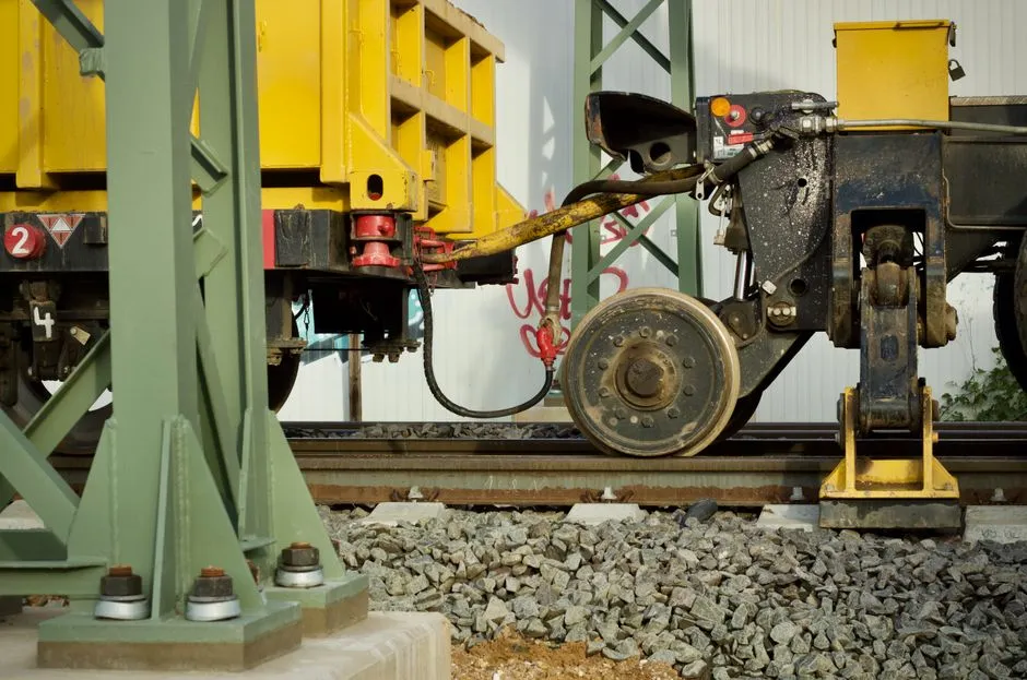
Mechanical alignment is the first physical gate; errors here propagate into every later phase and are the leading cause of bearing failure in the first 90 days of operation. Spirit-level the flotation tank across both diagonals to a tolerance of ≤2 mm/m — an uneven tank produces asymmetric flow and biased scum collection that no amount of process tuning can correct downstream. Laser-align the recirculation pump and motor shafts within 0.05 mm; misaligned couplings generate vibration, premature seal wear, and bearing failure that typically surfaces at 800-1,200 operating hours.
Pressurize the recirculation and air circuits to 1.5× working pressure (9 bar for a 6 bar saturator circuit) and hold for 30 minutes with zero pressure drop — this hydrostatic test catches flange and threaded joint defects before the system is filled with process water. Verify skimmer drive chain tension with a mid-span sag measurement: ≤10 mm is the typical OEM target; chains too tight stretch prematurely, chains too loose skip teeth under scum load. Record torque values on all flanged joints as a baseline (70 Nm for DN50, 110 Nm for DN80 is a typical reference range per ASME B16.5 class 150 flanges) and file them in the commissioning log. The skid-mounted chemical dosing system skids, where supplied, should be anchored and aligned on the same pad to keep dosing-line runs short.
Phase 2 — Water Tightness and Hydraulic Distribution
The water-tightness test confirms the tank and pipework hold water at design level for 24 hours with a leakage rate ≤0.1% of tank volume per hour — exceeding this indicates gasket, weld, or fitting defects that must be repaired before commissioning proceeds. Hydraulic distribution is the second key gate: dye-trace or flow-pad measurement across the full inlet width should show uniform velocity within ±10% of the mean. Dead zones covering more than 15% of the cross-sectional area indicate baffle adjustment is required; an uneven bubble curtain in operation almost always traces back to a Phase 2 distribution failure that was not caught at commissioning.
Confirm the outlet weir is level across its full length using a surveyor's level — a 5 mm tilt can drive 20% flow maldistribution between parallel cells in a multi-unit DAF. Calibrate the level sensor controlling the outlet valve or pump to ±5 mm accuracy; this instrument governs the sludge dryness at the surface and downstream solids loading, so instrument error here directly compromises performance test results. Test the scum trough drainage by pouring clean water at the design scum flow rate: the trough must clear within 30 seconds without overflowing back into the flotation zone. For background on how these hydraulic parameters interact with bubble contact, see the engineering breakdown in DAF process fundamentals.
Phase 3 — Saturator and Air Circuit Commissioning
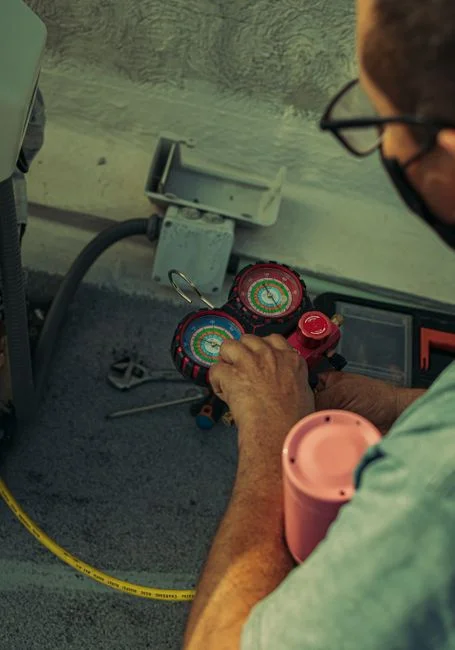
The saturator and air circuit is the most technical commissioning phase because it determines whether micro-bubbles of the correct size and quantity will form to carry solids to the surface. Begin with a pressure decay test: pressurize the saturator to 6 bar, isolate it from the pump and air supply, and measure pressure loss over 10 minutes. Acceptable decay is <0.2 bar/10 min; higher loss indicates a leaking check valve (component 10 per the S4 manual), loose fitting, or vessel defect. Then bring the recirculation pump online and verify the saturator reaches steady-state 4-6 bar within 5 minutes — pressure oscillation at this point typically means the air-inlet rotameter (component 29 per S4) is undersized for the design air-to-solid ratio.
| Test | Setpoint / Parameter | Acceptance Criterion | Common Failure Mode |
|---|---|---|---|
| Pressure decay (isolated) | 6 bar, 10 min hold | <0.2 bar loss | Check valve, fitting leak |
| Steady-state saturator | 4-6 bar within 5 min | Stable, no oscillation | Undersized air rotameter |
| Micro-bubble size | 30-50 µm (S4) / 50-100 µm (S3) | Visible dispersion across full inlet width | Worn pressure-reducing valve |
| A/S ratio | 0.02-0.05 kg air / kg solids | Matches jar-test-derived design value | Compressor undersized |
| Compressor duty | 360 L/min @ 10 bar (S4 reference) | Sustains pressure, not just at startup | Receiver tank too small |
Open the pressure-reducing valve to the flotation tank and visually confirm micro-bubble formation at the distribution hoses (components 18/1 per S4); the bubble size envelope should be 30-50 µm per the S4 manual or 50-100 µm per the S3 design pattern. Adjust the air-flow rotameter to deliver the design air-to-solid ratio (typical range 0.02-0.05 kg air per kg solids for TSS removal applications). Verify the air compressor can sustain saturator pressure under continuous duty — a compressor that only holds pressure at startup will fail within hours under real load. Lock the pressure regulator (component 25 per S4) at the design setpoint to prevent inadvertent over-pressurization. The saturator pressure envelope of 4-6 bar and recirculation range of 10-40% of total flow are the design anchors for the dissolved air flotation system.
Phase 4 — Process Commissioning with Real Influent
Transitioning from clean water to real wastewater is where commissioning failures most often surface, because hydraulic and chemical conditions now differ from the controlled Phase 2-3 environment. Start at 50% of design flow and ramp up to full design flow over 24-48 hours to avoid hydraulic shock to the developing floc blanket. Dose coagulant (typically PAC or alum at 50-150 mg/L) and anionic polyacrylamide flocculant (1-3 mg/L) per jar-test results; without jar testing, expect COD reduction in the 20-50% range rather than the upper end (per S3 design guidance).
Monitor floc formation in the optional coil-pipe flocculator — pin floc 2-4 mm in size is the target; smaller flocs will not adhere effectively to micro-bubbles and will pass through to the effluent. Set skimmer speed to a surface skim rate of 0.5-1.0 m/min; speed too high pulls clarified water with the scum (reducing sludge dryness), speed too low allows the sludge blanket to slump back into the clarified layer and degrade effluent quality. Confirm the recirculation rate at 10-40% of total flow using the recirculation pump flow meter — under-recirculation starves the system of micro-bubbles, over-recirculation wastes energy and shortens saturator contact time. Operating decisions made during this phase drive the long-term OPEX profile, which is itemized in the DAF OPEX breakdown for 2026.
Phase 5 — 72-Hour Performance Test and Handoff
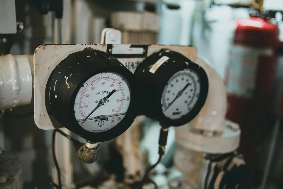
The 72-hour performance test is the formal acceptance gate that determines whether the client signs off and warranty coverage activates. Run the system at design flow ±10% for 72 continuous hours with no operator intervention beyond routine log entries; any unscheduled stoppage restarts the clock. Sample influent and effluent every 4 hours for TSS, COD, and FOG; passing requires ≥90% TSS removal and ≥95% oil and grease removal (per S3 design benchmarks). Verify effluent clarity at ≤15 NTU and sludge dryness of 3-4% DM by weighing a known volume of skimmed sludge after 1 hour of air-drying.
| Parameter | Test Condition | Pass Criterion | Notes |
|---|---|---|---|
| Test duration | 72 h continuous, ±10% of design flow | No unscheduled stoppages | Any restart resets the clock |
| TSS removal | Influent vs. effluent, 4 h interval | ≥90% | Average over 18 samples |
| FOG removal | Influent vs. effluent, 4 h interval | ≥95% | For oil-bearing applications |
| Effluent clarity | Final effluent | ≤15 NTU | Turbidimeter reading |
| Sludge dryness | Skimmed sludge, 1 h air-dry | 3-4% DM | Gravimetric |
Compile the commissioning report package: as-built drawings, signed-off checklist with all test data, instrument calibration certificates, and operator training records. This package is the warranty trigger for most OEMs and the legal record for the client. Hand over to operations with a written 30-day optimization window where chemistry and flow setpoints can be fine-tuned without invalidating performance acceptance — this protects both parties against the variability of real influent versus design assumptions.
Frequently Asked Questions
How long does DAF commissioning take for a packaged 50-200 m³/h unit?
A packaged DAF in the 50-200 m³/h range typically requires 5-10 working days from mobilization through performance test sign-off, assuming site readiness was completed in advance (HydropureWater field data, 2026). Multi-unit installations or sites with incomplete civil works run 2-3 weeks longer. Pre-delivery site checks save an average of 3-5 days versus discovering utility or pad issues after the equipment arrives.
What causes uneven bubble distribution across the flotation tank?
Uneven bubble distribution almost always traces to a Phase 2 hydraulic distribution failure: inlet baffle misadjustment, outlet weir tilt greater than 5 mm, or distribution hoses partially blocked. Verify with a dye-trace test at clean-water conditions before suspecting the saturator. If distribution is even on clean water but degrades with real influent, the cause is floc carryover into the distribution nozzles and the cure is upstream screening.
Can a DAF be commissioned without a chemical dosing system?
Yes, but with reduced performance. Physical flotation without coagulant typically achieves 40-70% TSS removal versus ≥90% with optimized chemistry, and is only suitable for low-loading, easy-to-float streams. For municipal or industrial wastewater, jar testing is mandatory before commissioning the chemical dose setpoints — otherwise the 72-hour performance test will fail the design TSS removal gate.
How is micro-bubble size verified without a particle size analyzer?
Visual inspection at the distribution hoses is the field method: a dense, milky-white dispersion with no visible large bubbles indicates bubble size in the 30-100 µm range. A laser particle sizer (e.g., Malvern Mastersizer) gives quantitative data but is rarely available on site. The functional check is whether the dispersion rises uniformly across the full inlet width within 2-3 seconds of pressure release.
Why does a DAF fail the 72-hour performance test after passing all earlier commissioning gates?
The most common cause is inadequate jar testing before commissioning — the coagulant/flocculant dose set during Phase 4 was not optimized for the actual influent variability, and effluent quality drifts during the 72-hour run as loading changes. Second most common is hydraulic overload: the upstream balancing tank is undersized and peak flows during the test exceed the design envelope by more than 10%. Both are correctable with a 30-day optimization window before final sign-off.