
Why Nanofiltration Systems Fail: The Five Recurring Failure Modes
Every NF failure on a plant floor reduces to one of five families: particulate and colloidal fouling, biofouling, scaling and precipitation, chemical oxidation (almost always free chlorine on polyamide), and mechanical or hydraulic faults like O-ring failure and permeate backpressure. The same SAMCO field review notes that RO and NF operate with the smallest pore sizes of any commercial membrane process, which is why they are "particularly prone to premature membrane fouling" when pretreatment or chemistry drifts. Because NF sits in a narrow operating window — pore size 0.5–5 nm, MWCO 200–1,000 kDa, feed pressure 4–30 bar, recovery 70–85% — it tolerates less abuse than UF but more than brackish RO. The same review also flags the 20–50% reject stream that NF systems produce as both a compliance risk for ZLD sites and a real water-purchase cost on every cubic metre of permeate. This article provides a guide for shift operators to read gauges, identify the active failure family, and act before a $4,000 element stack is scrapped.
Symptom-to-Cause Diagnostic Matrix: Read the Gauges Before You Touch the Skid
Most NF trips are diagnosed from three numbers on the HMI: feed-to-concentrate ΔP, normalized permeate flux, and permeate conductivity. Use the matrix below before you crack a pressure vessel. Typical NF baselines: feed pressure 4–30 bar, permeate flux 10–25 LMH, recovery 70–85%, single-pass ΔP 0.2–0.6 bar per stage. A ΔP rise greater than 15% from clean baseline over 30 days points to fouling, and a permeate conductivity increase greater than 10% points to scaling or membrane damage. Biofouling and scaling regularly coexist, so read both columns: a slimy, alkaline-CIP-reversible ΔP signature is biological; a chalky, acid-CIP-reversible flux loss is mineral. SAMCO's biofouling signature — "increased differential pressure from feed to concentrate, and decreased membrane flux" — is the cleanest field description available.
| Symptom (instrument reading) | Most likely cause | First check | First corrective action | Escalation threshold |
|---|---|---|---|---|
| ΔP up >15% baseline, flux stable or down 5–10% | Particulate/colloidal fouling | SDI₁₅, turbidity on NF feed | Backwash cartridge + MMF, verify coagulant dose | SDI₁₅ >5 for >24 h → forced CIP |
| ΔP up >15%, flux down >15%, slimy discharge | Biofouling | ATP swab, HPC count, biocide residual | Alkaline CIP pH 11–12, 35 °C, 60 min | No recovery in 48 h → element autopsy |
| Flux down >10%, conductivity up >10%, chalky | CaCO₃/CaSO₄ scaling | LSI/Stiff-Davis on concentrate | Acid CIP (0.2% HCl or 2% citric, 35 °C) | Recovery drops >5% absolute → re-dose antiscalant |
| Conductivity creep without ΔP change | Chemical oxidation / O-ring leak | Free Cl₂ feed, vessel pressure decay test | Neutralize Cl₂, replace O-rings | Permeate TDS > spec → element replacement |
| Reject volume creep from 30% to >45% | High system recovery pushed past scale limits | Antiscalant dose, concentrate LSI | Trim recovery 2–3%, re-dose antiscalant | >50% reject → engage RO polishing or ZLD |
Particulate and Colloidal Fouling: Pretreatment Is the Whole Game
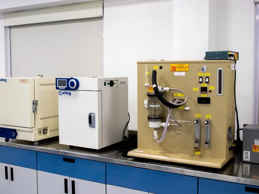
Roughly 80% of NF fouling events are decided by what happens upstream of the cartridge filter. The non-negotiable feed target for spiral-wound NF is SDI₁₅ below 5, and below 3 if you want to push recovery past 80%; turbidity should sit under 1 NTU at the NF inlet. The pretreatment train matches particle size to barrier: a rotary bar screen at 6 mm or finer, followed by a HydropureWater DAF system for suspended-solids and FOG removal for FOG and floatables, then a HydropureWater multi-media filter for SDI reduction rated at 20–50 µm, a 5 µm cartridge guard, and finally the NF vessel. For a greenfield or retrofit intake, a rotary bar screen at 6 mm aperture protects the DAF from rags and debris. SAMCO lists aluminum sulfate, aluminum chloride, sodium aluminate, and ferric chloride as common coagulants — all are effective, but overdosing carries aluminum or iron floc straight into the NF element, where it glues onto the membrane. Field rule: jar-test the dose weekly, and trim 10% if the filtered-water turbidity stops improving.
Scaling and Precipitation: Antiscalant Dosing Done Right
Scaling is the most predictable failure mode on an NF skid, and the fix is arithmetic. Calcium and magnesium are the dominant scale formers, with silica, barium sulfate, and strontium sulfate becoming real risks above 60% recovery. Three numbers gate every antiscalant decision: keep concentrate LSI below 0.5 (or Stiff & Davis Stability Index below 0 for high-TDS feeds), and silica below 150 mg/L as SiO₂ in the concentrate stream. Antiscalant dose scales with feed hardness — 1–5 mg/L for softened city water, 5–15 mg/L for moderately hard groundwater, and 15–30 mg/L for high-recovery industrial reuse or RO-polishing loops. A HydropureWater automatic chemical dosing skid for antiscalant and biocide with a flow-paced pump keeps the dose on target even as feed hardness drifts seasonally. When scale does break through, the CIP recipe is well established: 0.2% HCl or 2% citric acid at 35 °C, recirculated 30–60 minutes, then flushed to pH 5–6 before returning the train to service. Skipping the flush will precipitate the acid's iron load right back onto the membrane.
Biofouling: The Most Expensive Problem on the List
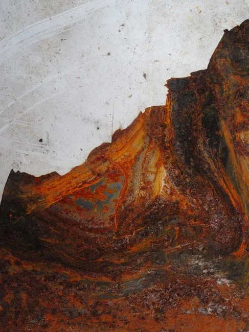
Biofouling is the NF failure mode that quietly doubles OPEX. Bacteria colonize a polyamide surface within hours, secrete extracellular polymeric substances within 24–48 hours, and form a mature biofilm that is 10–100× more biocide-resistant than the same organisms floating free in the bulk water. SAMCO states that RO and NF elements "provide the warm, low-flow environments suitable to biological growth" — and the worst offenders are recovery downtime, dead legs in the piping, and stagnant permeate blocks. A working defense has three layers. First, continuous feedwater oxidation with chlorine dioxide at 0.5–1.0 mg/L, delivered through a HydropureWater ClO₂ generator for polyamide-safe disinfection; ClO₂ is preferred over Cl₂ because it disinfects without attacking the polyamide active layer. Second, a weekly non-oxidizing biocide shock (DBNPA or isothiazolone) at the manufacturer's labelled dose, rotated quarterly to prevent resistance. Third, an alkaline CIP at pH 11–12 and 35 °C triggered the moment ΔP exceeds 15% of clean baseline — a high-pH wash hydrolyzes the EPS matrix and lifts the biofilm without damaging the membrane.
Chemical Attack: Why Polyamide NF and Free Chlorine Don't Mix
Polyamide is the workhorse NF and RO material because it rejects divalent ions at high flux, but it is the wrong choice wherever free chlorine is part of the upstream disinfection plan. SAMCO's warning is direct: "polyamide membranes are easily damaged by chlorine, making them a poor option in applications where chlorine is needed for disinfection purposes." The numeric envelope is tight — continuous free Cl₂ at the polyamide NF feed must stay below 0.1 mg/L, and cumulative exposure of roughly 1,000 ppm·h ends useful membrane life. The table below compares the three membrane materials, and the following design rule should be integrated into your P&ID.
| Property | Polyamide (PA) | Cellulose acetate (CA) | Polysulfone (PS) |
|---|---|---|---|
| Free Cl₂ tolerance | <0.1 mg/L continuous; ~1,000 ppm·h cumulative limit | ~1 mg/L continuous acceptable | 50–200 mg/L short-term acceptable |
| Operating pH range | 2–11 (cleaning 1–13) | 2–8 (limited) | 1–13 (broad) |
| Max temperature | 45 °C | 35 °C | 50–95 °C depending on grade |
| Rejection character | High divalent + significant monovalent | Lower overall, moderate divalent | Mostly used in UF/MF; limited NF grades |
| Typical NF use case | Industrial water reuse, RO polishing | Low-fouling feeds with Cl₂ present | Hot process streams, UF pretreatment |
Design rule: if upstream disinfection needs free chlorine, dose it, hold the contact time required, then reduce residual Cl₂ with sodium bisulfite at roughly 1.5× the stoichiometric chlorine residual before the NF feed. This preserves downstream polyamide life without sacrificing upstream biosecurity.
High Reject Volume: Engineering the Concentrate Problem
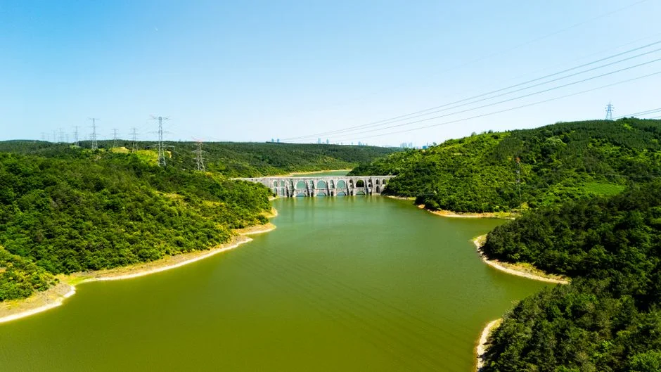
The 20–50% reject figure from SAMCO is a number the finance team will eventually ask about. Treat it as a decision tree, not a complaint. If the site has sewer capacity and an affordable discharge tariff, direct discharge of the concentrate is the lowest-OPEX option. If the site is on a zero liquid discharge permit, NF concentrate becomes the feed to an evaporator or crystallizer, and the conversation shifts to minimizing concentrate volume at constant NF recovery. The third branch — high disposal cost — is where OPEX math pays for the design change: trimming system reject from 35% to 20% on a 50 m³/h plant saves about 7.5 m³/h of combined water-purchase and discharge fees, or roughly $0.5–2/m³ depending on region — $9,000–$30,000 per month at industrial water rates. Two practical moves: step the NF recovery to 85–90% with a properly scaled antiscalant program, or add a HydropureWater industrial RO system for downstream polishing as a second pass that pulls another 60–70% of water out of the NF concentrate. The catch: pushing single-stage recovery above 90% without rigorous scale control shortens membrane life from about 5 years to roughly 2 years, and the element replacement cost — typically $25–40 per m² of membrane area — erases the OPEX saving inside one turnaround. The MBR vs SBR comparison for industrial wastewater provides further detail on how NF compares to biological alternatives.
Frequently Asked Questions
What SDI₁₅ should I target on the feed to a spiral-wound NF system?
Target SDI₁₅ below 5, and below 3 if you intend to run recovery above 80% or feed an RO polishing stage. Anything above 5 will drive ΔP up and shorten CIP intervals noticeably.
How much free chlorine will damage a polyamide NF element?
Hold continuous free Cl₂ at the NF feed below 0.1 mg/L and cumulative exposure below about 1,000 ppm·h. If upstream disinfection needs Cl₂, neutralize residual with sodium bisulfite at roughly 1.5× stoichiometric before the membrane.
What is the right CIP recipe for calcium carbonate scale on an NF membrane?
Circulate 0.2% HCl or 2% citric acid at 35 °C for 30–60 minutes, then flush to pH 5–6 before returning the train to service. An alkaline CIP at pH 11–12 is the right choice for biofouling, not scale.
How do I tell biofouling from scaling without pulling a membrane?
Biofouling shows a slimy