Pre-Installation: Document Handover and Pre-Shipment Inspection
Decanter centrifuge installation and commissioning is a four-phase protocol: (1) document and pre-shipment inspection, (2) foundation and mechanical alignment on a ≥C25 concrete base with ≤1 mm/m level tolerance, (3) ≥30-minute no-load trial verifying ≤40 °C bearing temperature rise and correct motor rotation, and (4) step-loaded commissioning with iterative tuning of drum speed, differential speed, pond depth, and flocculant dose. Acceptance requires signed-off KPIs for cake dryness, centrate clarity, vibration, and noise (70–80 dB(A) envelope) before production handover.
The day the crane arrives is not the day to discover a missing gasket. Before any rigging, the commissioning engineer should run a two-part receiving check against the order specification and the packing list. First, the document pack: instruction manual, certificate of conformity (COC), spare-parts list, control cabinet, inlet/outlet pipes, anchor bolts, and shock pads must all be physically present and match the line items (per S3 inspection checklist). Any discrepancy on the receiving report is the difference between a same-day equipment release and a two-week shipping claim.
Second, the internal condition. Open the observation port and visually confirm the drum, scroll, and bearing assemblies are clean, dry, and rust-free. Decanter bowls are typically shipped with a transport lock engaged to protect the differential gearbox — that lock must be released before any lifting. Running the machine with the transport lock still fitted destroys the planetary gearbox in under a minute.
For petrochemical, solvent-handling, or mining sites, verify the hazardous-area certification (NEC Class I Div 1 / ATEX Zone 1) on the nameplate matches the classified area drawing. S5 flags explosion-proof decanters as mandatory in these zones; a non-rated unit installed in a classified area is an immediate red-tag. Stage a Commissioning Document Pack on day one — P&ID, foundation drawing, GA drawing, electrical schematic, alignment report template, and lube schedule — so every signature line is ready when the contractor is on site.
Foundation Preparation, Lifting, and Mechanical Alignment
A decanter bowl generating up to 4,000 g of centrifugal force will find every weakness in the foundation, every soft shock pad, and every hard-plumbed pipe. The four numbers that define a serviceable base are concrete strength ≥C25, slab thickness ≥300 mm, natural cure ≥7 days before equipment placement, and a finished surface level of ≤1 mm/m (per S3). Anchor bolts must be set to drawing-specified hole diameter and depth, with pipe trenches, cable routes, and a maintenance access channel cast into the pour — retrofitting a missing cable trench after the slab cures means a jackhammer on day ten.
Lift only by the dedicated lifting lugs stamped on the frame. Hanging by the drum, scroll, or piping bends the shaft and scores the bowl shell. Nylon slings are preferred over wire rope to prevent cosmetic damage to the epoxy coat. Place the unit, then perform the first level check before the shock absorbers go in. After the rubber pads or spring isolators are loaded and the anchor bolts snugged up, repeat the level check — S3 explicitly requires a second survey post-shock-mount because spring deflection can tilt the frame by 0.3–0.5 mm/m that was not visible on the bare base.
Use spring washers under the anchor-bolt nuts and tighten in a star pattern to keep cyclic vibration from walking the nuts loose. The full-speed noise envelope is 70–80 dB(A) (per S5), which is acceptable at 1 m but irritating at the operator station — proper isolation is also an ergonomics issue, not just a vibration issue. Finally, connect feed, solids discharge, and centrate piping through flexible couplings or rubber bellows. A hard-plumbed connection transmits piping strain back into the bowl and shows up as bearing-housing vibration that has nothing to do with the rotor. For sites running a downstream plate and frame filter press for cake polishing, the centrate line flexible coupling is especially important because any pulsation from the press cycles back into the centrifuge pond.
| Parameter | Specification | Source / Notes |
|---|---|---|
| Concrete strength | ≥ C25 | S3 foundation spec |
| Slab thickness | ≥ 300 mm | S3 foundation spec |
| Cure time before loading | ≥ 7 days natural cure | S3 foundation spec |
| Surface level tolerance | ≤ 1 mm/m (re-check after shock-mounts loaded) | S3 |
| Anchor bolt washers | Spring type, tightened in star pattern | S3 |
| Piping connections | Flexible couplings on feed, solids, centrate | S3 / engineering practice |
| Full-speed noise envelope | 70–80 dB(A) at 1 m | S5 |
| Centrifugal force envelope | up to 4,000 g | S5 |
Electrical, Control, and Safety Interlocks
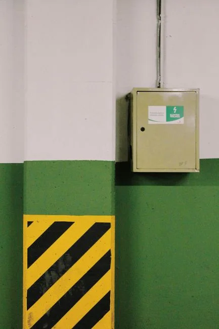
First energization is the highest-risk moment in a centrifuge commissioning. Wiring must be completed by a qualified electrician with a verified cabinet ground — high-frequency VFD common-mode noise on a floating ground is the number-one cause of spurious trips and encoder faults on initial start. Route VFD power cables and low-level signal cables on separate trays; cross only at 90° and never bundle in the same conduit. Heat, oil mist, and water vapor in cable trenches will degrade insulation faster than ambient-rated cables predict.
The polymer dosing system must be hard-interlocked to the centrifuge feed pump. S4 documents that dosing failure auto-stops the centrifuge to protect the scroll from torque spikes caused by under-conditioned feed. An automatic polymer dosing skid with its own PLC and flow-proportional output shortens this integration significantly. The knife-gate valve torque interlock should be wired in but released for manual override during early commissioning — S4's field experience shows automatic torque control misfires badly on variable sludge character and effectively hands control back to the operator for the first 24–48 hours of loaded running.
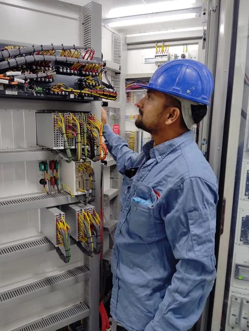
For hazardous-area sites, confirm before energizing that the control cabinet, motor terminal box, brake (if fitted), and any purge system carry the correct Class I Div 1 / ATEX certification matching the area classification. A LOTO (lockout/tagout) procedure and an arc-flash boundary calculation must be in the Commissioning Document Pack before any terminal is landed.
No-Load Trial Run: The Hard Gate Before Any Feed
The 30-minute no-load trial is the mechanical green light for feed. Three things must be verified, in order. First, on first power-on, confirm motor rotation matches the arrow on the housing. A reverse-rotated scroll at full speed is a destructive event — the differential protection and back-drive are designed assuming the rotation arrows are correct. Reverse any two phases at the disconnect before proceeding.
Second, run unloaded for ≥30 minutes while monitoring bearing housing temperature rise. S3 sets a hard limit of ≤40 °C rise above ambient on each bearing. Anything above that and the cause is usually under-lubrication, misaligned pillow blocks, or a damaged transport brace that was not fully removed. Listen for friction, impact, or grinding noise — any non-smooth acoustic signature is grounds to halt. Use a handheld vibration meter on each bearing cap; readings above the OEM baseline indicate residual imbalance that must be corrected before the next gate.
Third, cycle the differential gearbox, VFD, and back-drive (or hydraulic back-drive, depending on configuration) through the planned speed range while watching the HMI for alarm codes. Confirm lube-oil level in both the main gearbox and the back-drive gearbox — S4 dosing field data shows that dry-running an unfilled gearbox during commissioning is one of the most common causes of early bearing failure. Only after all three checks pass should any feed pump be started.
Step-Loaded Commissioning and Parameter Tuning
Once the no-load trial is signed, the real work begins. Step-load in three stages: 25 %, 50 %, then 75 % of design feed rate, holding each for 15–20 minutes while observing cake discharge, centrate clarity, scroll torque, and vibration. Do not jump to 100 % on day one — a feed ramp that is too aggressive will bury the operator in alarms before the parameter matrix is established.
The variable parameter matrix is the document the operator will live with for the next decade. Four levers matter; the rest are fixed by the machine geometry.
| Parameter | Effect When Increased | Tuning Trade-off | When to Adjust |
|---|---|---|---|
| Drum speed (VFD) | Higher g-force, faster settling, finer particle capture | Above critical speed, flocs are destroyed, vibration rises, power scales nearly linearly (S4) | Tune first, against cake dryness — not against VFD max |
| Differential speed (drum − scroll) | Higher throughput, wetter cake, lower scroll torque | Lower differential = drier cake, higher scroll torque, lower capacity (S4) | Tune second, after drum speed settled |
| Pond depth (weir plate) | Longer supernatant residence, clearer centrate | If too deep, supernatant overflows solids port and rewets cake (S4 / S5) | Adjust only at shutdown — bolted setting |
| Polymer / flocculant dose | Larger, stronger flocs, cleaner centrate, lower centrate TSS | Overdose wastes polymer OPEX and can glue the scroll; underdose starves the cake (S4) | Tune last, against centrate clarity and scroll torque stability |
| Knife-gate valve (during early commissioning) | Manual override recommended | Auto-torque control misfires on variable sludge (S4) | Hold manual for first 24–48 h loaded running |
On the polymer side, S4 recommends a fresh-water pressure of approximately 0.5 MPa to the eductor for consistent mixing, periodic tank-bottom cleaning to prevent settled solids from blocking the dosing line, and dosing-tank stock kept low enough to avoid moisture pickup hardening the dry powder. For operations planning a lamella clarifier installation and commissioning protocol upstream, the centrifuge polymer dose is best tuned after the clarifier has stabilized — feed solids character drives polymer demand almost one-for-one.
Commissioning Acceptance Criteria and Handover to Operations
Commissioning is not "done" when the centrifuge makes cake. It is done when the EPC and the client sign an acceptance matrix against measured numbers, not against a verbal "it looks good." Capture baseline KPIs at design feed rate: cake dryness (% DS), centrate TSS (mg/L), centrate visual clarity, vibration RMS at each bearing housing, and noise dB(A) at 1 m. Record polymer dose (kg active polymer per tonne dry solids) and specific power (kWh per m³ feed) as the OPEX baseline the operations team will be measured against for the next operating year.
Require a 72-hour unattended run log before final sign-off. Any knife-gate cycling, bearing-temp creep, or centrate-quality drift in that 72-hour window triggers a re-tune, not a sign-off. File as-built drawings, alignment report, no-load and loaded trial reports, lube schedule, and spare-parts list in the CMMS — these are the standard ISO 9001 / EPC documentation deliverables the procurement team will audit. Train operators on the three commissioning levers (speed, differential, pond depth) using the data captured in the Variable Parameter Matrix so they can repeat the tuning in 12 months when the feed character changes.
| KPI | Acceptance Threshold | Measurement Point | Sign-off |
|---|---|---|---|
| Cake dryness | Per contract spec (typical 18–28 % DS for biological sludge) | Cake discharge port, gravimetric | EPC + Client |
| Centrate TSS | Per contract spec (typically < 500–1,000 mg/L) | Centrate launder, lab TSS | EPC + Client |
| Bearing temperature rise | ≤ 40 °C above ambient | Each bearing housing, PT100 or handheld | EPC |
| Vibration RMS | ≤ OEM baseline at full speed | Each bearing cap, handheld or permanent monitor | EPC |
| Noise envelope | 70–80 dB(A) at 1 m (S5) | Operator station, Type 2 meter | EPC |
| Polymer dose | Site-specific baseline (kg/tDS) | Dosing skid flow totalizer / feed flow totalizer | Client |
| Specific power | Site-specific baseline (kWh/m³ feed) | Main motor kW meter / feed flow | Client |
| 72-hour unattended run | No alarm, no knife-gate cycling, no centrate drift | PLC event log + lab TSS check | EPC + Client |
Frequently Asked Questions
What concrete strength and level tolerance does a decanter centrifuge foundation require?
Decanter centrifuge foundations require a concrete strength of ≥C25, slab thickness of ≥300 mm, and a natural cure of ≥7 days before equipment placement. The finished surface must be level to ≤1 mm/m, with a second level check mandatory after the shock absorbers are loaded (S3 foundation spec).
How long should the no-load trial run before feed is introduced?
Run the decanter unloaded for at least 30 minutes, monitoring bearing temperature rise (≤40 °C above ambient), vibration, and motor rotation direction. A reverse-rotated scroll or a bearing temperature rise above the 40 °C limit halts commissioning until corrected (S3 trial-run protocol).
Which operating parameters should be tuned first during commissioning?
Tune drum speed first (against cake dryness, not VFD maximum), then differential speed (drum minus scroll, the cake-dryness vs. capacity trade-off), then polymer dose (against centrate clarity and scroll torque). Pond depth (weir plate) is a bolted setting adjusted only at shutdown, not in real time (S4 operating parameter hierarchy).
What hazardous-area certification is required for a decanter in a refinery or solvent plant?
Decanter centrifuges in flammable-vapor or dust environments require NEC Class I Division 1 / ATEX Zone 1 certified motors, control cabinets, and purge systems. Nameplate certification must match the classified-area drawing before energizing; non-rated equipment in a classified zone is an immediate red-tag (S5 explosion-proof decanter spec).
Related Equipment
- lamella clarifier for pre-thickening — specifications, capacity range, and technical data