
What AAO Process Installation and Commissioning Actually Covers
AAO process installation and commissioning is a staged engineering sequence that takes a newly built anaerobic-anoxic-oxic plant from mechanical handover to compliant effluent. Field data from a 50,000 m³/d multi-stage AAO plant in Shenzhen shows that with proper DO tuning, 90% of measured dissolved oxygen values fall within ±0.5 mg/L of setpoint (per Juntai precise-aeration commissioning case, 2025). The five stages are: equipment check, water and air testing, sludge seeding, process tuning, and 72-hour performance verification against discharge standards.
AAO (anaerobic-anoxic-oxic) is a suspended-growth biological nutrient removal configuration in which mixed liquor circulates through three redox environments in series: anaerobic for phosphorus release, anoxic for denitrification, and aerobic for carbon oxidation and nitrification. The multi-stage variant used in larger plants subdivides the aerobic and anoxic zones into independently controlled DO compartments, which is the architecture documented in the Shenzhen benchmark plant (2 biological tanks, 6 DO control zones per tank, 12 zones total, per Juntai 2025).
BSI BS EN 15287 frames commissioning as one of three linked phases — design, installation, and commissioning — meaning the commissioning plan must trace back to design intent, not be assembled in the field (per BSI BS EN 15287, 2026). In practice the five commissioning stages map to three operating modes: cold commissioning (dry, no water) covers stages 1–2 mechanical and hydraulic checks; wet commissioning (water, no biology) covers stage 3 sludge seeding; and performance commissioning (with biology) covers stages 4–5 DO tuning and the 72-hour acceptance test. For compact or skid-mounted variants, an integrated WSZ series packaged A/O treatment plant follows the same logical sequence on a compressed timeline.
Stage 1: Mechanical and Electrical Handover Checks
Mechanical and electrical handover is the only stage where the commissioning engineer can see every rotating component dry, and any defect not caught here will surface as a biological upset six weeks later. The goal is a clean punch-list signed by construction before any water touches the basin.
Walk the anaerobic-anoxic-oxic reactor with the construction manager and verify every internal sludge return pump, submersible mixer, decanter, and sludge scraper for correct rotation, free movement, and torque within nameplate range. Lock out each asset, confirm the direction arrow matches the rotation, and log a witnessed run of 30 minutes where the current draw stays inside the FLA band. Any pump drawing more than 110% of nameplate FLA under no-load mechanical run should be flagged for bearing or impeller inspection before water entry.
Check the aeration grid uniformity before the basin fills. Raise the diffuser drop pipes on the test rig, run a free air test, and record pressure drop across each branch. Flag any branch more than 10% above the average as a probable diffuser fouling or piping restriction defect and require replacement before commissioning continues. For blowers, the Shenzhen plant uses magnetic bearing centrifugal units (per Juntai 2025); verify each has an independent suction filter, isolation valve, and anti-surging pressure transmitter wired back to the master control cabinet.
Verify the instrument loop on each of the 12 DO zones matches the hardware map: one online DO analyzer per zone, one thermal gas flow meter on the branch pipe, one electric control valve (per Juntai precise-aeration configuration, 2025). Cross-check against the I/O list and reject any loop where the tag numbers do not reconcile.
Finally, the construction manager must hand over a red-line P&ID and a signed I/O list before the team touches the biology. Screening equipment upstream of the AAO reactor — such as a rotary fine bar screen — should already be commissioned at this point, since a ragging event on day 14 of seeding will wipe out the microbial community you are trying to grow.
| Check | Acceptance Criterion | Source |
|---|---|---|
| Internal pump and mixer rotation | Matches nameplate arrow; current within 90–110% FLA on 30-min run | Standard pre-commissioning practice |
| Aeration branch pressure drop (free air) | Each branch within ±10% of branch average | Engineering rule of thumb |
| Blower anti-surge transmitter | Wired to master cabinet; trip testable in stage 2 | Juntai 2025 (Shenzhen case) |
| DO zone instrument loop | 1 DO analyzer + 1 thermal gas flow meter + 1 electric valve per zone | Juntai 2025 |
| Pre-commissioning screening | Bar screen commissioned upstream of biological tanks | Standard practice; e.g. rotary mechanical bar screen |
Stage 2: Water-Fill, Leak, and Aeration Distribution Tests
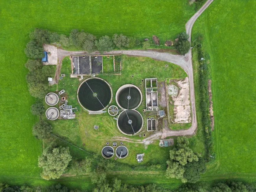
Stage 2 proves the civil tank, pipework, and aeration hydraulics under load — but still without biology. Any leak, trapped air pocket, or uneven air distribution that survives this stage will be very hard to diagnose once mixed liquor is in the basin.
Fill the basins in three steps — typically 1/3, 2/3, and full — and hold each level for at least 24 hours while watching structural joints and pipe penetrations for seepage. Document any wet patch with a photograph, GPS stamp, and a leak rate (mL/min) so the construction manager has a quantitative close-out target rather than a verbal "we'll fix it."
Run the blowers in manual mode at minimum speed and measure airflow branch by branch with a portable pitot tube or the installed thermal gas flow meters. Each DO control zone should receive air within ±10% of its design value; anything outside that band indicates a balancing or diffuser problem. Confirm DO analyzer response by dipping each probe in air-saturated and de-aerated reference solutions, recording the slope and zero, and rejecting any probe whose output falls outside the manufacturer's stated accuracy band (typically ±0.1 mg/L for luminescence-quenching probes at 25°C).
Test each electric aeration valve from the central control workstation in both manual and remote modes — this is the two-mode valve control architecture described in the Shenzhen commissioning protocol (per Juntai 2025). Verify that a manual command from the HMI moves the valve, that a remote (precise aeration) command moves it on a setpoint, and that the position feedback tracks the command within 2 seconds.
Trip-test the anti-surging pressure interlock by simulating a sudden downstream valve closure; the master control cabinet must drop the blower to a safe turn-down within the surge time constant of the machine. Chemical dosing skids for phosphorus precipitation or pH correction are usually commissioned in parallel with the aeration hydraulics; a PLC-controlled chemical dosing skid can be flow-paced against the same influent signal that drives the aeration model.
Stage 3: Sludge Seeding and Acclimation
Sludge seeding is where most AAO projects lose the most calendar days, because the temptation to push load on day 5 is strong and the microbial community does not forgive a shock. The objective of this stage is to grow a stable, dispersed, nitrifying floc without inviting filamentous opportunists.
Seed the aerobic zone with return activated sludge (RAS) from a healthy donor plant, or with a commercial seed product, to reach an initial MLSS of 2,500–3,500 mg/L. The anoxic and anaerobic zones do not need direct seeding — they receive mixed liquor via internal recirculation (typically 100–200% of influent flow). Set the initial SRT to 8–12 days; once nitrification is established and NH₃-N removal is consistently above 90%, raise SRT to 15–25 days for stable simultaneous nitrification-denitrification.
Feed the plant at 30% of design load for the first 5–7 days, using either actual influent blended 1:1 with potable water or a dilute substrate recipe (e.g. glucose + ammonium chloride + potassium phosphate). This gives the biomass time to acclimate to the specific wastewater matrix without driving a high F/M shock. During seeding, hold DO in the aerobic zone at 1.5–2.0 mg/L — high enough to keep the floc aerobic, low enough to discourage grazing protozoa and filament overgrowth. The Shenzhen plant operated at setpoint with 90% of readings inside ±0.5 mg/L (per Juntai 2025); use that as a calibration target rather than a free-running value.
Monitor SV30 and SVI every 12 hours, and run a microscopic examination at the same cadence. A healthy seed at the end of week 1 shows a dispersed floc with scattered stalked ciliates and a few free-swimming ciliates; SVI should sit between 80 and 150 mL/g. Pin floc (SVI < 50 mL/g), high SVI above 200 mL/g, or persistent nocardioform foam are all signs of a failed seed — the corrective action is to waste from the aerobic zone and reseed rather than wait for the system to "settle down," because filamentous populations, once established, take 2–3 SRT cycles to wash out. Sludge wasted during seeding must be dewatered; a small plate-frame filter press sized to the seeding waste rate avoids hauling liquid sludge off-site.
| Parameter | Seeding Target (Days 1–7) | Acclimated Target (Day 14+) |
|---|---|---|
| Aerobic MLSS | 2,500–3,500 mg/L | 3,000–4,000 mg/L |
| SRT | 8–12 days | 15–25 days |
| Loading | 30% of design | Ramp 50 → 80 → 100% |
| Aerobic DO | 1.5–2.0 mg/L | 2.0–3.0 mg/L |
| SVI | 80–150 mL/g | 80–150 mL/g |
| Microscopy endpoint | Dispersed floc, scattered stalked ciliates | Dispersed floc, stalked + free-swimming ciliates |
Stage 4: DO Setpoint and Aeration Tuning
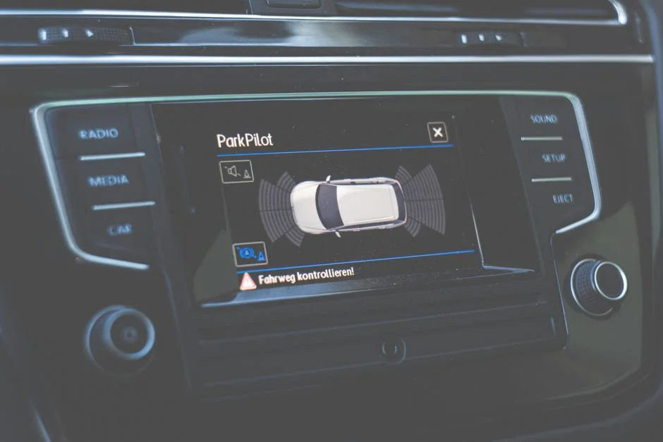
Stage 4 is where the precise aeration system earns its name: six independently controlled DO zones per tank, all driven from one workstation, all pulling from the same blower. Get this stage right and the rest of the 14-day window is calm; get it wrong and the operator will spend the next year chasing swings.
Set the DO setpoints for simultaneous nitrification and denitrification: anaerobic zone < 0.2 mg/L, anoxic zone 0.2–0.5 mg/L, aerobic zone 2.0–3.0 mg/L. The Shenzhen plant runs 6 independently controlled DO zones per tank — a pre-anoxic compartment, a downstream anoxic compartment, and four aerobic compartments — to give the aeration controller enough granularity to track an ammonia peak through the train (per Juntai 2025).
The precise aeration software runs a "feedforward + feedback + model" loop: feedforward signals are influent flow and influent load; feedback signals are DO, MLSS, and tank level; the model translates those into a per-zone air demand (per Juntai 2025). On top of that, the controller uses a multi-valve decoupling strategy so that opening one branch valve to raise DO in zone 3 does not collapse DO in zone 4 — this is the field-proven decoupling approach described in the Shenzhen commissioning procedure.
Verify blower behaviour in this stage. The system should hold the most economical blower turn-down while keeping pipeline pressure above the surge line. The Shenzhen plant uses magnetic bearing centrifugal blowers that accept real-time setpoint changes from the precise aeration workstation (per Juntai 2025); conventional blowers with inlet guide vanes need slower ramps to avoid surge. If the blower surges during tuning, switch the precise aeration system to manual mode immediately and reset the valve sequencing — the Shenzhen protocol explicitly lists this as a commissioning contingency.
Accept the tuning stage when DO in each of the 12 zones holds within ±0.5 mg/L of setpoint for 24 consecutive hours. That band is the same 90% probability reported in the Shenzhen trial operation (per Juntai 2025). Foam on the aerobic tank during tuning is a common symptom of high SRT or surfactant load — see How to Solve Foam Control in Wastewater Treatment (2026 Guide) for the remediation steps.
Stage 5: 72-Hour Performance Test and Acceptance
The 72-hour performance test is the contractual handover between commissioning and operations, and the engineer's only defensible record of compliance. Run it as a structured protocol, not as "see how it goes for three days."
Run the plant at 80%, 100%, and 110% of design load for a minimum of 24 hours each within the 72-hour window, in that order. Keep influent flow and quality within ±20% of design values across the entire test — outside that band, the precise aeration control cannot be validated and the result is meaningless (per Juntai 2025). If the influent cannot be held inside that band, postpone the test rather than invalidate the data.
Sample influent and effluent for COD, BOD₅, NH₃-N, TN, TP, and TSS using 24-hour composite auto-samplers, with at least one grab sample per shift to catch diurnal swings. Compare against the discharge standard — the Shenzhen plant was designed to meet China Surface Water Class IV (per Juntai 2025), which is roughly COD ≤ 30 mg/L, NH₃-N ≤ 1.5 mg/L, TN ≤ 15 mg/L, TP ≤ 0.3 mg/L; substitute the local equivalent (e.g. EPA 40 CFR 133 for US POTWs) where the project is sited. Record DO accuracy across all 12 zones for the full 72 hours; the headline acceptance metric is 90% of readings within ±0.5 mg/L of setpoint (per Juntai 2025).
At the end of the test, issue a snag list with a 30-day close-out window, and only sign the Taking-Over Certificate after the construction manager has transferred O&M manuals, PLC source code, training records, and a calibrated instrument register. Sedimentation equipment downstream of the AAO reactor — often a tube settler or lamella clarifier — is part of the same compliance envelope; review Tube Settler Clarifier vs Alternatives: 2026 Engineering Comparison with Cost, Efficiency & Compliance Data for the sizing context that supports the effluent TSS number.
| Test Condition | Duration | Influent Stability | Acceptance Metric |
|---|---|---|---|
| 80% design load | ≥ 24 h | Flow & quality within ±20% of design | Effluent meets discharge standard; DO 90% within ±0.5 mg/L |
| 100% design load | ≥ 24 h | Flow & quality within ±20% of design | Same |
| 110% design load (peak) | ≥ 24 h | Flow & quality within ±20% of design | Same; check NH₃-N breakthrough |
| Composite sampling | Every 24 h per condition | COD, BOD₅, NH₃-N, TN, TP, TSS | Class IV (or local equivalent) compliance |
Common Commissioning Failures and How to Prevent Them
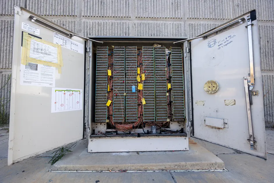
Most AAO commissioning failures repeat across projects because they are symptoms of a sequencing mistake, not an equipment failure. Walk in already inoculated against the top three.
Blower surging during initial valve/blower coordination is the single most common mechanical upset. The Shenzhen commissioning protocol prescribes keeping DO in manual mode until valve sequencing has been verified end-to-end (per Juntai 2025); the same discipline applies to any blower type. Foaming on aerobic tanks during high-SRT operation or surfactant shock is the second most common issue and is fully treatable — see How to Solve Foam Control in Wastewater Treatment (2026 Guide) for the antifoam-and-wasting protocol. Filamentous bulking from low F/M during low-load commissioning is the third: hold MLSS by wasting from the aerobic zone only, never from the return line, so the SRT stays in the 15–25 day band. Finally, DO probe drift underestimates true DO and starves nitrification — re-calibrate probes weekly for the first 60 days, then monthly, and keep a spare calibrated probe in the cabinet.
For a deeper dive on biological failures and MBR-side troubleshooting, MBR Common Problems and Solutions: 2026 Engineering Troubleshooting Guide covers the membrane-side analogues (fouling, cake formation, foaming) that often surface during parallel commissioning of an MBR polishing stage.
Frequently Asked Questions
How long does AAO commissioning take from mechanical handover to compliant effluent?
A typical multi-stage AAO plant takes 14 to 30 days: about 3–5 days for mechanical handover and water/air testing, 7–10 days for sludge seeding and acclimation, 3–5 days for DO tuning, and 3 days for the 72-hour performance test. The Shenzhen 50,000 m³/d multi-stage AAO benchmark ran this sequence end-to-end inside that envelope (per Juntai 2025).
What DO setpoints should I use for simultaneous nitrification and denitrification?
Set the anaerobic zone below 0.2 mg/L, the anoxic zone at 0.2–0.5 mg/L, and the aerobic zone at 2.0–3.0 mg/L. The Shenzhen plant runs 6 independently controlled DO zones per tank to give the precise aeration controller enough granularity to hold these bands under load swings (per Juntai 2025).
What is the MLSS target during AAO start-up and seeding?
Seed the aerobic zone with return activated sludge to reach 2,500–3,500 mg/L MLSS initially, then hold 3,000–4,000 mg/L once the system is acclimated. Pair this with an SRT of 8–12 days during seeding and 15–25 days once nitrification is established — operating outside those bands risks pin floc or filamentous bulking.
What is the DO accuracy I should accept before signing off the tuning stage?
Accept the tuning stage when DO in each zone holds within ±0.5 mg/L of setpoint for 24 consecutive hours. In the Shenzhen 50,000 m³/d trial, 90% of measured DO values fell inside that ±0.5 mg/L band with the precise aeration system active, and 30% fell inside ±0.3 mg/L (per Juntai 2025).
When can I run the 72-hour performance test, and what load steps should I cover?
Run the test only after the tuning acceptance metric is met and influent flow and quality can be held within ±20% of design values. Step the plant through 80%, 100%, and 110% of design load for at least 24 hours each, sample COD, BOD₅, NH₃-N, TN, TP, and TSS, and sign off only when all parameters meet the local discharge standard (per Juntai 2025).
Related Equipment
- MBR bioreactor system — specifications, capacity range, and technical data