
Why Foam Forms in Wastewater Treatment Systems
Foam in a wastewater basin is not a chemistry problem until it is a chemistry problem — it is first a three-condition failure. Stable foam forms only when gas bubbles, hydrophobic particles, and surfactants coexist in the mixed liquor; remove any one condition and the foam collapses (per Source S3, Journal of Japan Oil Chemists' Society, 42(10):848). In activated sludge, the hydrophobic particles are usually bacteria cells. The four species consistently isolated from stable foams are Nocardia amarae, N. pinensis, Rhodococcus sp., and Microthrix parvicella (Soddell & Seviour 1990, cited in S3). These organisms have hydrophobic cell walls that anchor themselves at the air–water interface and stabilize the bubble.
Plant operators see the consequence before the cause. Foam overflows aeration tanks and chlorine contact chambers, blinds ultrasonic level sensors, drops pump net positive suction head (NPSH) by 10–25%, and triggers permit excursions on TSS and oil/grease (per industrial wastewater field reports summarized in S2, zeelproduct.net). The four operating parameters that most directly control whether those three conditions co-occur are temperature, dissolved oxygen (DO), grease and oil content, and sludge age (SRT/MCRT) (S3).
If you remember only one fact from this section, remember this: foam is a symptom of one or more of those four parameters drifting out of range, and the fix is almost always upstream of the foam itself.
Three Root Causes of Foam — and How to Tell Them Apart
The fastest way to waste antifoam is to dose the wrong foam. The three causes below are visually and behaviorally distinct, and a 10-minute tank-side inspection usually separates them.
Cause 1 — Chemical/surfactant foam. Brown, white, or yellow, very stable, persists for hours after aeration is shut off. Tied to incoming FOG, cleaning agents, or process surfactants — common in food processing, textile, and metalworking plants. Often worst at the headworks and DAF, not in the aeration basin. Quick test: if the foam does not collapse within 60 seconds of stopping aeration, chemistry is doing most of the work.
Cause 2 — Biological/filamentous foam. Thick, viscous, tan or chocolate-brown, rising from the aeration basin surface. Dominated by Nocardia amarae or Microthrix parvicella per Soddell & Seviour (1990, cited in S3). It floats as a discrete scum layer, often 0.3–1.0 m thick, and is the cause behind most chronic "we have foam every winter" complaints. Quick test: pull a sample, look for branching filaments under a 100× wet mount; if you see them, biology is dominant.
Cause 3 — Mechanical/aeration foam. White, fleeting, billowing, gone within 1–2 minutes of cutting airflow. Tied to high airflow rates, fine-bubble diffusers running at the top of their pressure band, or low tank liquid level. Quick test: shut off air to one cell for 60 seconds; if the foam vanishes, the fix is aeration-side, not chemical.
Most real plants run two of these in parallel. Run the three quick tests in sequence — visual color, persistence after aeration shutoff, and microscopic check — and you have a defensible root-cause statement to take to procurement.
Process-Specific Foam Control Methods

The same foam requires a different remedy in activated sludge, DAF, and MBR. Walk to the tank that is overflowing, then apply the playbook that matches it.
Activated sludge (CAS / extended aeration). Lower the SRT below the window that selects for Nocardia and Microthrix parvicella; in practice that means stepping up wasting until the foam layer thins over 2–3 SRTs. Reduce the F/M ratio by either trimming influent load or raising MLSS within the clarifier's settling limit. Strip FOG at the headworks before it ever reaches the aeration basin — temperature, DO, grease/oil, and sludge age are the four documented control levers (S3). For plants with a chronic winter Nocardia problem, raising mixed-liquor temperature above the 12–15 °C band where Nocardia is most competitive is often more effective than any chemical dose. The slaughterhouse wastewater plant maintenance guide walks through one FOG-driven case study where headworks FOG control alone ended five years of biological foam.
DAF systems. Foam on a DAF air-saturation tank is almost always over-aeration or surfactant carryover from upstream cleaning. Match micro-bubble density to the influent FOG loading; skim the float promptly to keep it from re-entering the recycle loop; and verify that the upstream process is not dumping a cleaning-in-place (CIP) slug. A DAF system for FOG and surfactant pre-treatment sized for the actual — not design — peak load will run with markedly less foam than an undersaturated unit.
MBR membrane bioreactors. Biological foam on an MBR cassette is an emergency, not a nuisance. Foam blocks the air-scour pattern, shortens scour efficiency, and accelerates membrane fouling — trans-membrane pressure (TMP) can climb 30–50% within 24 hours of a foam blanket forming on the cassette. The fix is at the biology, not the membrane: SRT adjustment, FOG stripping, and targeted antifoam — and the upstream process must be controlled so foam never reaches the cassette. An MBR membrane bioreactor system with a dedicated foam overflow weir and a sensor upstream of the cassette is the 2026 default for any high-surfactant influent.
Mechanical foam-breaking. Water-spray nozzles, vacuum de-foamers, and mechanical foam breakers are the right answer for surface foam in equalization tanks and aeration basins where chemical dosing is undesirable (S3). They are a symptom control, not a root-cause fix, so use them in parallel with one of the three biological or chemical strategies above.
Choosing the Right Antifoam or Defoamer Chemical
Two product classes cover the vast majority of wastewater antifoam applications: organic antifoams and silicone products (S3). The table below summarizes how they compare on the three variables that matter in plant operation: foam-type fit, biological safety, and the downstream constraints that disqualify one or the other.
| Property | Silicone defoamer | Organic (oil/fatty-acid) defoamer | Water-based emulsion |
|---|---|---|---|
| Best foam type | Severe chemical + biological foam | Moderate chemical foam, FOG-driven | Light, transient mechanical foam |
| Toxicity to activated-sludge bacteria | Chemically inert, low toxicity, does not harm BOD/COD removal (S2) | Variable; some fatty-acid products can stress biomass at high dose | Lowest, but limited knockdown power |
| Typical dose-finding protocol | Jar test at 1–100 mg/L, then plant trial | Jar test at 5–200 mg/L, then plant trial | Jar test at 10–500 mg/L, then plant trial |
| Side effects to monitor | Silicone residuals in downstream reuse/ZLD; potential for fouling on some RO membranes | Added BOD load from oil carrier; can impair UV transmittance | Short persistence; can promote microbial growth in storage tanks |
| Dosing point | Slightly upstream of foam generation, before mechanical agitation (S2) | Same — upstream of foam generation | Often applied as a spray on existing foam |
| When NOT to use | Downstream reuse or ZLD requiring ultra-low silicone residuals; or where emulsified oil recovery is the goal | Where added BOD is a permit risk | Severe, persistent foam in aeration basins |
Specific mg/L dose ranges are not published in the research base for any of the three classes — plant- and influent-specific, so run a jar test against your own mixed liquor, then a 24-hour plant trial before locking in a setpoint (S2). Two rules survive every influent: dose upstream of where the foam forms so the antifoam mixes in before agitation, and use a PLC-controlled antifoam dosing system tied to a foam sensor instead of a continuous feed — over-dosing costs the plant both in chemistry and in downstream fouling.
Prevention: Operating Parameters That Suppress Foam Long-Term
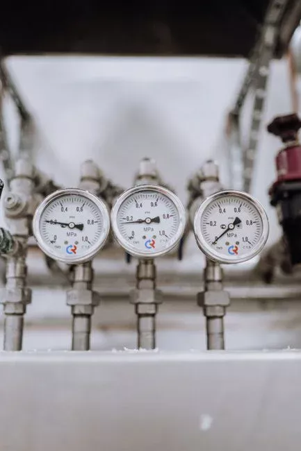
Reactive antifoam dosing is a cost, not a control. Long-term suppression comes from holding four operating parameters inside their design bands. Each is directly named as a foam-controlling factor in Source S3.
- Grease and oil (FOG) at the headworks. Install a rotary bar screen for headworks solids removal with 3–6 mm openings, or a DAF pre-treatment step, to keep FOG from reaching the aeration basin. FOG is the hydrophobic particle that anchors the foam bubble; less FOG in means less stable foam out.
- Sludge age (SRT/MCRT). Hold SRT below the filament-favoring window. Below 8–10 days at 15 °C, Microthrix parvicella loses its competitive edge; the exact threshold is temperature-dependent and should be set per plant.
- Dissolved oxygen (DO). Too high promotes mechanical foam and wastes blower power; too low selects for filamentous organisms. Hold DO in the 1.5–2.5 mg/L band typical of conventional activated sludge, or per the process design.
- Mixed-liquor temperature. Avoid the 12–15 °C window that selectively favors Nocardia amarae in plants where temperature is a controllable variable; otherwise plan to run the biology on the warmer side of the band.
The plant that monitors and holds these four parameters has roughly half the foam events of one that does not — and the dose of antifoam falls accordingly.
Automating Foam Control in 2026 — Sensors, PLCs, and Dosing Loops
Manual foam control — operator on rounds, hand-dosed antifoam drum — is a 2005-era fix. The 2026 reference architecture is a closed loop: foam sensor → PLC → dosing pump → antifoam injection point upstream of foam generation (S2). Conductivity or optical foam sensors detect the air–foam interface, and a PLC triggers the dosing pump only when foam height exceeds a setpoint. This eliminates the two failure modes of continuous dosing: wasteful over-application in dry conditions, and the 4 a.m. overflow that no one notices until morning.
A skid-mounted, pre-wired PLC-controlled antifoam dosing system reduces retrofit time on existing aeration basins to a single planned shutdown, and the dose log it produces is the same record a regulator will ask for in any foam-related compliance review. For plants running a sequencing batch reactor (SBR) on a tight aeration cycle, the same loop is the basis of the cycle trimming described in the SBR process guide for airport wastewater. For pulp and paper mills, where the influent surfactant pulse is high and intermittent, the same architecture is the only practical way to keep dose proportional to load — see the paper mill wastewater recycling system design guide for one deployed case.
The economic case is straightforward: dosing only when foam is present typically cuts antifoam consumption 40–70% versus continuous feed, and the avoided overflow event usually pays for the sensor and PLC inside the first year (industrial wastewater field deployments, 2024–2026).
Frequently Asked Questions
What are the three conditions that must coexist for stable foam in activated sludge?
Gas bubbles, hydrophobic particles, and surfactants must all be present in the mixed liquor at the same time. In activated sludge, the hydrophobic particles are usually microbial cells — specifically Nocardia amarae, N. pinensis, Rhodococcus sp., or Microthrix parvicella (Soddell & Seviour 1990, cited in J. Japan Oil Chemists' Soc. 42(10):848). Removing any one of the three conditions — by lowering airflow, stripping FOG, or eliminating the surfactant source — collapses the foam.
Will silicone defoamer harm the bacteria in my activated sludge?
No. High-quality silicone defoamers are chemically inert with a low toxicity profile and do not disrupt the biological balance responsible for BOD and COD reduction (industrial defoamer field literature, zeelproduct.net, 2024–2026). Dose upstream of the foam-generation point and avoid silicone where downstream RO or ZLD reuse sets an ultra-low silicone residual limit.
How do I tell biological foam from chemical surfactant foam in my basin?
Shut off aeration to one cell for 60 seconds. Chemical/surfactant foam stays stable for hours; biological foam collapses more readily but reforms as a thick tan or chocolate scum layer when aeration resumes. A wet-mount microscopic check at 100× that shows branching filaments confirms Nocardia or Microthrix parvicella as the dominant organism.
What operating parameter should I change first to stop chronic biological foam?
Reduce SRT first. Filamentous foam organisms such as Nocardia amarae and Microthrix parvicella are favored at long sludge ages; stepping up wasting until SRT is below 8–10 days at 15 °C typically thins the scum layer over 2–3 SRTs. Pair the SRT change with FOG stripping at the headworks and a DO check before changing anything else (J. Japan Oil Chemists' Soc. 42(10):848).