Why Jacksonville Transportation Equipment Plants Cannot Discharge Straight to the Sewer
Transportation equipment plants near Jacksonville, FL meet pretreatment limits before sewer discharge by routing every industrial stream through a process train sized to satisfy 40 CFR Part 403 categorical standards and JEA Industrial Pretreatment Program local limits. In practice this means oil/water separation plus DAF for FOG and TSS, pH adjustment with chemical dosing, and biological polishing via MBR or activated sludge before the JEA collection system connection.
40 CFR 403.3(k) defines interference as a discharge that, alone or in conjunction with other sources, inhibits or disrupts the POTW, its treatment processes, or its sludge handling — and is a cause of an NPDES permit violation. In a plant, that translates to a slug of cutting oil, a pH excursion below 5, or a hex-chrome spike that kills biomass in the JEA aeration basins. 40 CFR 403.3(p) defines pass-through as a discharge that exits the POTW into waters of the U.S. in concentrations that cause a violation of the POTW's own NPDES permit — a 50 mg/L FOG plume into the St. Johns River is the textbook example. Either one is a direct EPA enforcement hook against the Industrial User (IU).
Jacksonville is served primarily by separate sanitary sewers (per EPA's municipal wastewater page), and I/I is a chronic operational issue. That means any industrial slug hits the JEA plant hard with no dilution buffer from stormwater — the receiving water's first defense is the IU's own pretreatment, not the collection system. The 2024–2025 enforcement climate in Jacksonville confirms regulator pressure is active: a Jacksonville wastewater plant was placed under state penalty for compliance violations, which is a signal to JEA IUs that the local limit enforcement chain is functioning and pretreatment sampling at the point of connection is being scrutinized. Any transportation equipment plant discharging to JEA is a Significant Industrial User (SIU) when process flow exceeds 25,000 gpd, per 40 CFR 403.3(j), and that triggers full SIU self-monitoring, slug-control plan, and 24-hour composite sampling obligations.
The Three-Layer Compliance Stack: Federal Categorical, 40 CFR 403, and JEA Local Limits
Federal categorical pretreatment standards sit at the top of the stack and set numerical effluent limits by industry subcategory. Most transportation equipment plants classified under NAICS 336 fall under 40 CFR Part 432 (metal finishing) for conversion coating, plating, and chemical milling streams, or 40 CFR Part 433 (metal products) for parts washing, machining, and assembly wastewaters. Each subcategory has its own daily maximum and monthly average limits for metals, FOG, TSS, and pH.
Layer 2 is 40 CFR Part 403 — the General Pretreatment Standards. These are not numerical but prohibit any discharge that causes pass-through or interference under 40 CFR 403.5. They also enumerate absolute prohibitions: no cyanide, no flammable solvents, no pH below 5.0, and no slug loads. Layer 3 is the JEA Industrial Pretreatment Program local limits — site-specific numeric or narrative limits developed under 40 CFR 403.5(c) to protect the receiving POTW, its sludge, and the St. Johns River. JEA's local limits are typically tighter than the federal categorical standards for FOG, hexavalent chromium, and total metals because the JEA plant's biological treatment is sensitive to those specific loadings.
EPA enforces local limits developed under 40 CFR 403.5(c) at the end-of-pipe discharge from the IU — the point of connection to the POTW's collection system, not at the IU's headworks (per EPA's pretreatment local-limits guidance). That distinction is the most common audit finding: an IU that samples at the headworks and shows compliant numbers, but whose actual point-of-connection discharge is out of limits because of a side stream or a bypass. The audit implication is that the sampling port location must match the discharge point in the JEA permit, and the slug-control plan must cover every side stream that can reach the connection.
| Layer | Authority | What It Controls | Form | Audit Risk If Missed |
|---|---|---|---|---|
| 1. Federal Categorical | 40 CFR Parts 432 / 433 | Industry-specific numerical limits (metals, FOG, TSS, pH) | Daily max / monthly avg | Notice of Violation, NOV |
| 2. General Pretreatment | 40 CFR 403.5 | Pass-through, interference, prohibited discharges | Narrative prohibitions | EPA enforcement under 403.5 |
| 3. JEA Local Limits | 40 CFR 403.5(c) | Site-specific FOG, Cr(VI), metals loadings | Numeric end-of-pipe limits | JEA NOV, permit revocation |
For engineers who work on adjacent sectors, the same three-layer logic applies — see how Lakewood textile and dyeing plants meet pretreatment limits under a similar federal + state + POTW stack.
Wastewater Streams a Transportation Equipment Plant Actually Generates
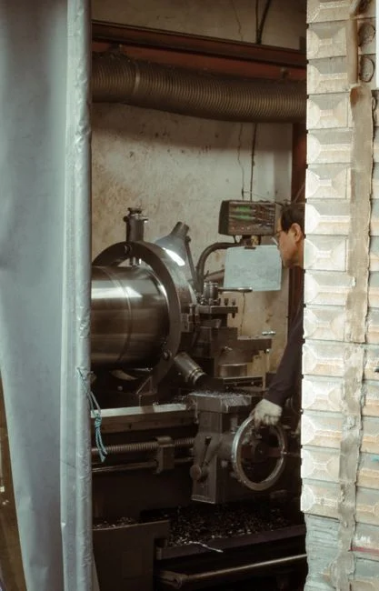
Four canonical streams dominate the ETP influent at a NAICS 336 plant. Stream 1 is oily machining coolant and parts-washer water — the largest volume contributor, carrying FOG at 500–5,000 mg/L, TSS at 200–2,000 mg/L, and trace metals from tool wear (Ni, Cr, W). Stream 2 is phosphate conversion coating and chromate rinse water — typically low volume but high in total phosphate, hexavalent chromium (Cr(VI)) up to 50 mg/L, zinc, and nickel. Stream 3 is paint booth and waterborne coatings washwater — high in COD (1,000–10,000 mg/L), suspended paint solids, and solvents. Stream 4 is boiler blowdown and cooling-tower bleed — moderate in TDS, high in temperature, and cycled for water reuse before discharge.
Flow batching matters: most JEA IU permits require equalization tanks sized for at least one shift of peak process flow, typically 8 hours at peak hourly flow, so the ETP can absorb a batch dump from a phosphate coating line without slugging the biological stage. Cyanide-bearing streams from some heat-treat operations are absolute prohibitions under 40 CFR 403.5 and require segregated treatment — cyanide cannot be routed to a chrome-reduction tank because the reaction chemistry conflicts and any residual cyanide reaching the JEA plant is a categorical violation.
| Stream | Dominant Pollutants | Typical Concentration | Batch Strategy | Critical Concern |
|---|---|---|---|---|
| Oily machining coolant / parts washer | FOG, TSS, trace Ni/Cr/W | FOG 500–5,000 mg/L; TSS 200–2,000 mg/L | Continuous with EQ surge | FOG slug → JEA biomass upset |
| Phosphate / chromate rinse | Cr(VI), Zn, Ni, PO₄ | Cr(VI) up to 50 mg/L | Batch with segregated tank | Cr(VI) pass-through to St. Johns |
| Paint booth washwater | COD, paint solids, solvents | COD 1,000–10,000 mg/L | Batch on booth dump events | Solvent interference at JEA |
| Boiler blowdown / CT bleed | TDS, temperature, scale inhibitors | TDS 500–2,000 mg/L | Continuous, cooled | Thermal plume, high pH excursions |
The 2026 Pretreatment Process Train: From Oily Inlet to Discharge-Ready Effluent
The process train below is sized for a 50,000 gpd (≈190 m³/d) plant and aligns with the unit operations JEA permits expect to see on the IU's process flow diagram. Step 1 is a rotary mechanical bar screen with 3–6 mm bar spacing to remove rags, plastics, and parts debris before they reach the pump station. Step 2 is an equalization / pH buffer tank with PLC-controlled chemical dosing for pH adjustment to 6.5–8.5 and cyanide destruction via alkaline chlorination if any heat-treat stream is present. Step 3 is a dissolved air flotation unit that handles the FOG and TSS load — micro-bubbles (20–80 μm) attach to oil droplets and float them to the surface for automatic skimming, with a typical capacity range of 4–300 m³/h. DAF is the right call for FOG and TSS — see the comparison in DAF or clarifier for fabricated metals wastewater for the engineering reasoning.
Step 4 is chemical precipitation in a pH-adjustment reactor followed by a lamella clarifier for heavy metals removal (Cr, Ni, Zn). Cr(VI) is first reduced to Cr(III) with sodium metabisulfite or ferrous sulfate at pH 2–3, then precipitated as Cr(OH)₃ at pH 8–9 alongside the other metals. Lamella surface loading is typically 20–40 m/h per the equipment spec, and sludge recirculation from the clarifier bottom improves precipitate growth. Step 5 is an MBR membrane bioreactor for COD/BOD polishing — 0.1 μm pore size, effluent turbidity typically <1 NTU, and roughly 60% smaller footprint than conventional activated sludge at the same loading. Step 6 is sludge dewatering with a plate and frame filter press (1–500 m² filtration area range, PLC-operated) to bring the DAF float and lamella sludge to a 25–35% dry solids cake for off-site disposal.
Step 7 is optional ClO₂ disinfection if the receiving POTW has a bacterial limit — JEA sometimes requires fecal coliform <200 CFU/100 mL for food-grade-adjacent IUs or IUs that share a sub-basin with food processors. The full train is automated with a PLC that interlocks chemical dosing pumps to flow meters and pH/ORP probes, which is what JEA's slug-control plan language expects to see. For operational troubleshooting of the MBR stage — trans-membrane pressure creep, sludge bulking, winter viscosity — the field guide to MBR common problems and solutions covers the typical failure modes.
| Step | Unit Operation | Target Pollutant | Key Parameter | Source |
|---|---|---|---|---|
| 1 | Rotary bar screen | Solids, debris | 3–6 mm bar spacing | Field practice, 2026 |
| 2 | EQ / pH buffer + chemical dosing | pH, cyanide | pH 6.5–8.5; 8 h peak EQ | Per JEA permit |
| 3 | DAF | FOG, TSS | 4–300 m³/h, 20–80 μm bubbles | HydropureWater catalog, 2026 |
| 4 | Lamella clarifier + precipitation | Cr, Ni, Zn | Surface loading 20–40 m/h | HydropureWater field data, 2026 |
| 5 | MBR | COD, BOD, residual solids | 0.1 μm pore, <1 NTU effluent | HydropureWater field data, 2026 |
| 6 | Plate and frame press | Sludge volume | 1–500 m² area, 25–35% DS | HydropureWater catalog, 2026 |
| 7 | ClO₂ disinfection (optional) | Fecal coliform | <200 CFU/100 mL | Per JEA permit |
Sizing for Compliance: Parameter Table for a 50,000 Gpd Jacksonville Plant
The table below maps each major stream to its design flow, key pollutant, JEA local limit (or 40 CFR Part 432 limit where categorical applies), target unit operation, and expected effluent. The 50,000 gpd figure is the trigger threshold for SIU status under 40 CFR 403.3(j) — any plant above it carries the full SIU self-monitoring and slug-control obligation. The 25% safety margin built into the MBR polish stage reflects the EPA definition of pass-through under 40 CFR 403.3(p) — the ETP must discharge at concentrations low enough that JEA's own NPDES permit is not put at risk by residual loadings after the JEA plant's treatment.
40 CFR 403 local limits are reviewed annually and must be re-evaluated periodically per EPA guidance, which means a plant designed tight against 2026 numbers needs headroom for 2027–2028 tightening. Plan for at least 20–30% design margin on the MBR flux rate and the DAF surface loading to absorb limit revisions without a capital retrofit. Equipment sizing below anchors to the DAF catalog range of 4–300 m³/h and the MBR range of 10–2,000 m³/day (HydropureWater catalog, 2026), so a 190 m³/day plant sits comfortably mid-range for both unit operations.
| Stream | Design Flow (m³/d) | Key Pollutant | Typical Influent | JEA / 40 CFR Limit | Target Unit Operation | Target Effluent |
|---|---|---|---|---|---|---|
| Oily machining coolant | 80 | FOG, TSS | 2,000 / 1,000 mg/L | 100 mg/L FOG (JEA) | DAF | <50 mg/L FOG |
| Phosphate / chromate rinse | 30 | Cr(VI), Zn, Ni | 30 / 15 / 10 mg/L | 0.1 mg/L Cr(VI) (JEA) | Reduction + lamella | <0.05 mg/L Cr(VI) |
| Paint booth washwater | 40 | COD, TSS | 5,000 / 800 mg/L | 40 CFR 432 limits | EQ + MBR | <100 mg/L COD |
| Boiler blowdown / CT bleed | 40 | TDS, temperature | 1,500 mg/L | JEA narrative | Cooling + bypass EQ | <500 mg/L TDS |
| Combined ETP effluent | 190 | COD, TSS, FOG, Cr(VI) | — | End-of-pipe (JEA) | MBR polish | Meets all JEA limits |
2026 Compliance Checklist Before JEA Renewal
- Confirm the discharge characterization report reflects current production — JEA requires a re-baseline whenever categorical applicability changes, and adding a new chrome plating line or paint line triggers it.
- Verify 24-hour composite sampling is at the point of connection (not the headworks) per the EPA local-limits enforcement rule under 40 CFR 403.5(c) — the sample port location is the most common audit finding.
- Confirm the slug-control plan is current, signed, and physically posted at the discharge sampling station; review it annually at minimum.
- Confirm SIU self-monitoring reports for the past 12 months are on file with JEA in the format JEA's electronic reporting system requires, and that any non-detect values are flagged ND with method detection limits.
For a worked example of what a 2026 acquisition-triggered compliance refresh looks like in practice, see the GM Texas plant acquisition wastewater compliance guide.
Frequently Asked Questions
What categorical standard applies to a Jacksonville transportation equipment plant with both a phosphate coating line and a paint booth?
40 CFR Part 432 (Metal Finishing) governs the phosphate coating rinse water with subcategory-specific limits for Cr(VI), Zn, Ni, and PO₄. Paint booth washwater may be covered by Part 432 or Part 433 depending on whether the painting is part of a finishing sequence or a separate forming operation. A baseline monitoring report per 40 CFR 403.12(b) is required to confirm the applicable subcategory before the JEA permit is issued.
How tight are JEA's local limits for FOG and hexavalent chromium compared to federal categorical standards?
JEA's local limit for FOG is typically 100 mg/L daily maximum at the point of connection, and Cr(VI) is commonly set at 0.1 mg/L — both tighter than the corresponding 40 CFR Part 432 metal finishing values in many subcategories. The tightening is justified under 40 CFR 403.5(c) to protect the JEA plant's biological treatment and the St. Johns River receiving water, and it is enforced as a pretreatment standard by EPA at end-of-pipe.
When does an Industrial User become a Significant Industrial User under JEA's program?
Per 40 CFR 403.3(j), an IU is a Significant Industrial User when process wastewater flow exceeds 25,000 gpd, or when it has a categorical standard, or when JEA determines that slug discharge, pass-through, or interference potential warrants SIU oversight. For a 50,000 gpd transportation equipment plant, all three triggers typically apply, and the SIU self-monitoring, slug-control plan, and 24-hour composite sampling obligations all activate.
Can a plant skip the MBR stage and discharge DAF effluent directly to the JEA collection system?
No. DAF alone typically achieves 50–80% FOG and TSS removal but leaves COD at 500–1,500 mg/L and does not address soluble metals. JEA's local limits for COD and residual metals at end-of-pipe will not be met by DAF alone for a transportation equipment plant. MBR polishing, with its 0.1 μm pore size and <1 NTU effluent, is what brings COD below 100 mg/L and residual Cr(VI) below detection — the pass-through definition under 40 CFR 403.3(p) is the regulatory basis for the polish stage.