
Why Electrocoagulation Cells Fail in Industrial Service
Electrocoagulation (EC) cells fail in three predictable places, and recognizing which surface is breaking is the difference between a 30-minute fix and a week of wasted pilot work. The reaction is straightforward in operator terms: a sacrificial iron or aluminum anode dissolves into the water, releasing metal ions that hydrolyze into a hydroxide floc; the floc coagulates suspended and dissolved contaminants while hydrogen gas bubbles generated at the cathode float solids to the surface (ITRC S5, 2021). When the system works, the effluent clarifies and the floc settles or floats cleanly. When it does not, the failure is almost always feed chemistry, electrical control, or downstream separation — not the reactor itself.
Feed-side failures cluster around two parameters: pH and conductivity. ITRC documents the effective operating window as pH 4–8 (Adhoum et al. 2004 via S5). Below pH 3, iron and aluminum stay soluble and no floc forms at all (S5). Conductivity must be high — ITRC states the technique requires sufficient dissolved ions to carry current (S5). On the electrical side, passivation, current density, and electrode gap are the variables an operator can verify in ten minutes. On the separation side, EC's output is a coagulated sludge that must be removed in a dedicated dewatering or clarification step (S5) — the cell is only one of three required systems.
For reference benchmarks: TSS removal can reach 95–99%, TDS reduction 27–60% (Powell Water Systems 2009 via S5), copper 90–100% in the ACE pilot (Barkley et al. 1993 via S5), and chromium 87–94% in the same study. If your cell is producing no visible floc, the train is not even running the chemistry that delivers these numbers.
Symptom-to-Cause Diagnostic Map
When the EC cell "fails" on shift, the operator needs a triage table, not a textbook. The map below pairs each visible symptom with the most likely root cause and the first check that resolves it. Work the table top-down — feed-side checks come before electrical, electrical before separation, because the cheapest tests run first.
| Symptom | Most Likely Cause | First Check / Fix |
|---|---|---|
| Black or dark effluent | Sulfate reduction to sulfide at cathode (Basha et al. 2007 via S5) | Confirm feed sulfate; document reducing conditions; add downstream aeration if sulfide carryover is a concern |
| No visible floc | Feed pH below 3 keeps Fe/Al soluble (S5) | Measure feed pH; pre-neutralize with caustic to bring pH into 4–8 |
| pH climbing above 8.5 | Hydroxyl accumulation at cathode from water reduction (S5) | Verify polarity-reversal cycle; dose feed acid to hold 4–8 window |
| Low current at rated voltage | Passivated anode (oxide layer) or scaling | Reverse polarity, inspect electrode surface, replace anode if wear >30% |
| White/frothy overflow | Chloride–organic feed generating chlorinated byproducts (S5) | Confirm feed chloride; consider anode change or pre-treatment |
| High TSS in clarifier overflow | Downstream separator overloaded (surface overflow rate too high) | Reduce flow to DAF/lamella; verify floc is actually forming in reactor |
Two of these symptoms deserve operator attention. A pH climb to 9 or 10 is a documented ITRC finding caused by excess hydroxyl ions at the cathode once metal ions in solution are depleted (S5) — it is not a sensor glitch, it is the chemistry telling you the cell is stripping its load. A black effluent reading on a sulfate-bearing feed is the CECRI smelter case: Basha et al. (2007) reported blackening from metal sulfide precipitation as sulfate was reduced at the cathode, with Cu removal still hitting 98.8% (via S5). The color is a side reaction, not a fault, but the downstream operator needs to know sulfide is present.
Feed-Side Checks: Conductivity, pH, and Contaminant Loading

The cheapest, fastest checks live upstream of the cell, and most EC faults live there too. Walk this list before opening the electrical panel. Measure feed conductivity with a portable meter; if it sits in the low range (operators commonly target a working value well above the threshold where current stalling becomes visible — typically a few thousand µS/cm for most industrial feeds), dose electrolyte. Sodium chloride is the standard pick because chloride also supports the anode dissolution reaction. ITRC's S5 wording is unambiguous: "the conductivity of the contaminated water must be high."
Confirm pH is in the 4–8 window (Adhoum et al. 2004 via S5). Below 4 you will burn anode metal for no floc return; above 8 you start losing the soluble metal species that drive coagulation. ITRC also notes that EC works "more efficiently when lower concentrations of pollutants are present" (S5) — very high contaminant loads may require pre-dilution, staged cells, or both. If sulfate is part of the feed matrix, document it: the cathode can reduce sulfate to sulfide (Basha et al. 2007 via S5), which produces a black precipitate and a small hydrogen sulfide risk in confined spaces.
For mixed-metal feeds above pH 3, expect the pH to rise toward neutral as metal hydroxides precipitate. The Aachen 2006 pilot on a Serbian smelter feed climbed from pH 4.3 to 7 while removing Cu 99.9%, Al 97.7%, Mn 99.7% (Rodriguez et al. 2007 via S5) — that pH drift is the cell working, not failing. Track the trend, not the absolute number.
Electrical & Electrode Checks: Current, Polarity, and Passivation
If feed-side checks pass, move to the reactor. The first read is the panel: is DC current at the rated setpoint, or is it sagging? ITRC states that "typically direct current (DC) is required" (S5), so on a DC system a low-current-at-rated-voltage reading points to one of three things — a passivated anode, a failed rectifier, or a low-conductivity feed that already failed the upstream check.
Passivation is the most common electrode-side failure. A thin oxide film builds on the cathode, raises resistance, and chokes current. ITRC notes that AC technology "may prevent formation of an oxide layer on the cathode" (S5) — for DC skids, polarity reversal on a 15–60 minute cycle is the equivalent preventive practice and is now standard on 2026 PLC-controlled units. Inspect the gap between plates; ITRC lists electrode gap as a key adjustable parameter (S5), and a warped plate can short a cell or starve it of current density.
Electrode wear is by design — Fe and Al anodes are sacrificial. ITRC explicitly lists "regular replacement of electrodes" as a known limitation (S5). Track anode mass or thickness over time; once wear exceeds roughly 30% of original mass, plan a swap before removal efficiency drops. As an energy benchmark, the CECRI copper smelter case used 10.99 kWh/kg of total heavy metal removed (Basha et al. 2007 via S5). If your kWh/kg is dramatically higher, something is wrong electrically — likely passivation, a gap issue, or a rectifier fault.
One more electrical-side caution from S5: in feeds with chlorides and organic pollutants, EC can oxidize chloride and chlorinate the organics into toxic byproducts. If you are treating brine, produced water, or any saline organic stream, factor this into your chemical risk review and consider a pre-treatment step.
Downstream Separation: The Most Misdiagnosed 'EC Failure'
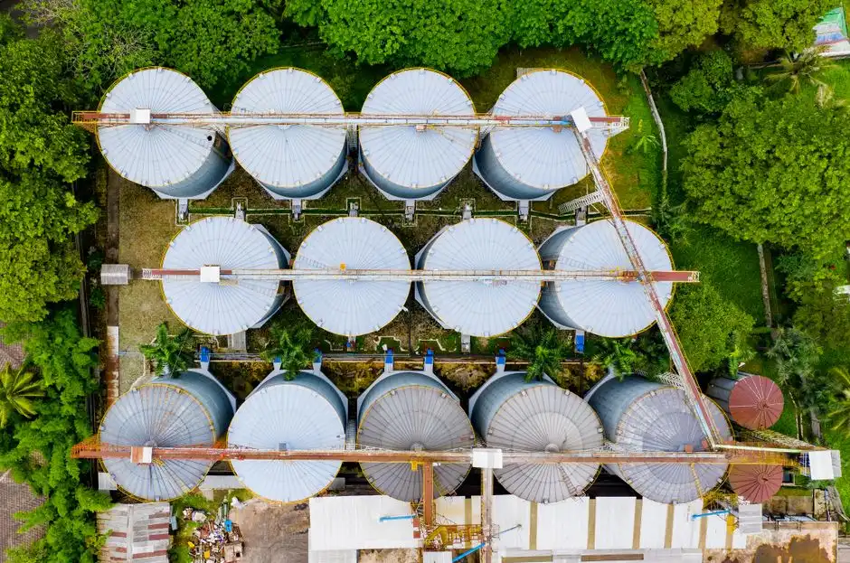
The single most common EC misdiagnosis is blaming the cell when the floc is being lost in the clarifier or DAF. ITRC lists three required systems — reaction chamber, electrical system, and "a system to dewater the precipitated/coagulated solids" (S5). When the third system is undersized or mistuned, the EC reactor can be working perfectly and the plant still discharges turbid effluent.
The good news is that EC floc is robust. ITRC states the floc generated is "larger and heavier and settles out better than in conventional chemical precipitation processes" (S5) — which is why a properly tuned gravity clarifier can handle it. If your floc is overflowing a lamella, the surface overflow rate is too high for the hydraulic load, not the chemistry. If the floc is buoyant — lots of attached H2 bubbles from the cathode reaction — a DAF separator for electrocoagulation floc is the right downstream choice; a lamella clarifier for heavy EC floc fits when the floc is dense and settles. The recovered sludge is generally lower in volume than chemical-precipitation sludge and easier to dewater (S5), which means a downstream filter press or centrifuge captures that advantage.
Run this check before tearing into the cell: pull a side-by-side sample of reactor outlet and clarifier overflow. If the reactor outlet is already turbid, the cell is the problem. If the reactor outlet is clear and the clarifier overflow is turbid, the cell did its job and the separator is the problem.
Field Fix Playbook: Seven Data-Backed Corrective Actions
The diagnostic above reduces to seven actions an operator can execute this shift. Each is tied to a documented mechanism and a measurable outcome.
| # | Fault | Fix | Mechanism / Source |
|---|---|---|---|
| 1 | pH drift above 9 | Enable polarity reversal or dose feed acid | Hydroxyl accumulation at cathode (S5) |
| 2 | No floc, pH < 3 | Caustic pre-neutralization to pH 4–8 | Fe/Al soluble below pH 3 (S5) |
| 3 | Low current at rated voltage | Inspect electrodes, reverse polarity, replace anode if wear >30% | Passivation / sacrificial wear (S5) |
| 4 | Low conductivity | Dose NaCl to raise conductivity | Conductivity must be high (S5) |
| 5 | Black effluent on sulfate feed | Document reducing conditions; add downstream aeration if sulfide carryover is a concern | Cathodic sulfate reduction to sulfide (Basha et al. 2007 via S5) |
| 6 | Chlorinated byproduct risk | Switch anode material or pre-treat to remove chlorides | EC can chlorinate organics (S5) |
| 7 | High TSS breakthrough downstream | Reduce clarifier/DAF surface overflow rate; confirm reactor is producing floc | Third system sizing (S5) |
Fix 1 and Fix 4 are where most shift-level interventions land. A PLC-controlled chemical dosing system for pH and conductivity correction takes both off the operator's hands and ties them to a logged trend rather than a manual check. Operators chasing related faults in adjacent trains will also find the lime dosing troubleshooting playbook useful for the pH-correction side, and the UF membrane troubleshooting guide for polishing steps downstream of the EC/clarifier pair.
Preventive Maintenance Schedule for 2026 EC Skids

Firefighting on EC cells is more expensive than scheduled care. A 2026 PLC-controlled skid logs most of what you need, but the operator still owns the inspection.
- Daily. Log feed conductivity, pH, applied current, and applied voltage against the ITRC 4–8 pH window (S5). Trend the four numbers; a drift is a warning before it is a fault.
- Weekly. Inspect electrodes for scaling, pitting, and passivation. Confirm the polarity-reversal cycle is active and matching the set interval (S5).
- Monthly. Weigh a sacrificial coupon or measure anode thickness to forecast replacement; ITRC lists electrode replacement as a known maintenance load (S5).
- Quarterly. Validate the downstream separator against baseline TSS removal. ITRC reports 95–99% TSS potential (Powell Water Systems 2009 via S5) — if you are not in that band, the third system needs attention, not the reactor.
- Annual. Run a third-party jar test or pilot confirmation to verify site-specific removal rates still match the design basis. ITRC recommends "detailed bench and pilot studies" prior to implementation (S5); the same logic applies to revalidation.
Frequently Asked Questions
What pH range does electrocoagulation work in?
Electrocoagulation works in the pH 4–8 window per ITRC S5 (Adhoum et al. 2004). Below pH 3, iron and aluminum stay soluble and no floc forms. Above pH 8, induced pH drift from cathode hydroxyl generation can push the effluent to pH 9–10 (S5).
Why is my electrocoagulation cell producing no floc?
Three causes cover most no-floc events: feed pH below 3 keeping Fe/Al soluble (S5), feed conductivity too low to support current, or passivated electrodes choking the anode reaction. Check pH first, then conductivity, then electrode condition.
How often do electrocoagulation electrodes need replacement?
ITRC lists "regular replacement of electrodes" as a known limitation of EC (S5). For Fe/Al anodes running at typical industrial current densities, replacement cycles fall in the months-to-quarters range depending on load, current density, and whether polarity reversal is in use.
Can electrocoagulation remove chromium?
Yes. The ACE pilot reported 87–94% chromium removal (Barkley et al. 1993 via S5), though ITRC notes that chromium and silver may require long retention times and are aided by co-precipitation with other metals.
What downstream separator pairs with electrocoagulation?
ITRC lists a dewatering or separation system as the third required component of an EC train (S5). Dense, heavy EC floc pairs well with a lamella clarifier; buoyant, H2-laden floc pairs better with a DAF unit. Sludge from either path is generally lower in volume and easier to dewater than chemical-precipitation sludge (S5).