
Lime dosing troubleshooting starts with three failure modes that dominate roughly 80% of industrial installations: slurry blockage, inaccurate flow, and loss of pump prime. A Yorkshire Water site cut downtime by 65% after moving to peristaltic pumps and holding slurry line velocity above 1.5 m/s to limit settling.
Lime dosing troubleshooting: top root causes
Lime dosing systems usually fail from slurry settling when line velocity drops below 1.2 m/s, from wet-end wear beyond a ±5% error band, and from air leaks that break suction prime. Keep 10–15% Ca(OH)₂ slurry above 1.5 m/s, flush high-use lines every 72 hours, and seal suction joints under a 1 mm leak path.
Over 70% of lime dosing failures originate from slurry settling or crystallization in lines, especially when flow velocity drops below 1.2 m/s, as reported by Top 1 and ResearchGate users. That threshold matters for particle suspension: hydrated lime (Ca(OH)₂) slurry at 10–15% solids settles quickly once transport velocity is lost. The abrasive solids then accelerate wear on diaphragms, check valves, and seats.
Inaccurate dosing, often showing as a ±15% deviation from target, commonly follows degraded diaphragms in mechanical pumps handling abrasive Ca(OH)₂ slurry. Repeated flexing against fine lime particles creates micro-cracking and fatigue, so volumetric accuracy drifts. Most plants we size for continuous slurry service see the worst drift after several months at the upper solids end of the 10–15% band.
Pump priming problems are often made worse by air trapped in slurry tanks when agitators run outside a narrow window. Paddle speeds below 20 rpm may leave solids settled; speeds above 30 rpm can pull a vortex and drag air into the suction line. Holding paddle speed at 20–30 rpm suspends solids without entraining air, as verified by HydropureWater field data. For a broader view of the lime dosing process in water treatment explained, separate the preparation train from the dosing train before you chase pump faults.
Symptom 1: Slurry Blockage in Piping and Pumps
Slurry blockages occur most frequently in low-point elbows and short horizontal runs, so high-use systems need inspection and flushing every 72 hours. Lime settles, then crystallizes into hard carbonate scale that pinches flow. Short horizontal pockets and dead legs are the usual culprits, not the full pipe length.
To clear an existing plug, a 20% citric acid solution (pH 2–3) for 30 minutes dissolves calcium carbonate scale. Follow the acid soak with a high-velocity water rinse above 2 m/s to scour loosened solids and residual acid. Use proper PPE and ventilation for any chemical flush.
For lasting prevention, specify minimum 1.5-inch diameter Schedule 80 PVC or 316L stainless steel piping for abrasion and corrosion resistance. Install every slurry line with a continuous slope greater than 2% so the line drains fully and stagnant pockets disappear. Holding transport velocity above 1.5 m/s keeps particles suspended, matching the Yorkshire Water result. Industry lime-handling guidance also frames a practical velocity band of 1.2–3 m/s and warns against letting VFD turndown push flow below a 1.2 m/s floor (WaterSMART, 2018).
| Parameter | Recommendation | Rationale |
|---|---|---|
| Minimum Slurry Velocity | >1.5 m/s | Prevents settling and crystallization of Ca(OH)₂ particles. |
| Pipe Material | Schedule 80 PVC or 316L SS | Resists abrasion from lime slurry and chemical corrosion. |
| Minimum Pipe Diameter | 1.5 inches | Reduces shear stress and likelihood of localized settling. |
| Minimum Pipe Slope | >2% (continuous) | Ensures complete drainage, eliminating stagnant zones. |
| Flushing Frequency | Every 72 hours (high-use) | Removes nascent scale and settled solids proactively. |
Symptom 2: Inconsistent or Inaccurate Dosing Output
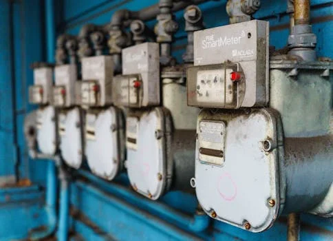
Dosing pumps that drift beyond ±5% of target flow usually point to worn check valves or diaphragm fatigue. Confirm accuracy with a calibrated bucket-and-stopwatch test over 5 pump strokes. Any deviation above ±5% is a trigger to open the wet end, not to trim the PLC setpoint alone.
Diaphragm pumps tend to lose 10–15% of capacity after 6 months in continuous lime slurry service because of micro-cracking and material loss. Plan diaphragm replacement every 12 months, or add pressure-decay monitoring so integrity loss shows up before the next compliance sample fails. Where plants need tighter delivery, precision lime slurry dosing specs usually start with wet-end materials and stroke verification, not a larger pump.
Stroke length or frequency settings that disagree with the actual PLC output account for incorrect dosing in 30% of systems, as per Verito Engineering case data. Walk the loop: confirm the controller output, the local stroke dial, and the measured bucket volume on the same day. Most intermittent “mystery underdose” tickets we see close after that three-way check.
Symptom 3: Pump Won’t Prime or Loses Prime Frequently
A 1 mm gap in suction fittings or foot-valve seals can admit enough air to break the siphon and explains about 90% of priming failures on lime slurry duty. Inspect every suction joint for weeping, white lime crust, or loose unions. Tiny air ingress is enough to empty the pump chamber on restart.
Install a vent valve at the highest point of the suction line and bleed it manually before startup so the chamber fills with liquid. Keep the slurry tank outlet submerged at least 300 mm below the liquid surface to stop vortexing and air entrainment. That submergence rule is cheap insurance compared with chasing phantom pump faults.
How is lime dosing applied in wastewater?
Lime dosing in wastewater treatment injects a prepared Ca(OH)₂ slurry into the process stream under pH feedback so alkalinity rises and metals or acidity drop to the permit target. Typical milk-of-lime strength for plant dosing stays in the 10–15% solids band for pumpability and stable control response. OSMRE mine-drainage guidance notes modern hydrated-lime systems can reach about 38% solids by weight.
The control loop is simple on paper and unforgiving in the field: a downstream pH probe trims stroke length or frequency on the dosing pump. Probe fouling, lag in the reaction tank, and slurry concentration drift all look like “pump problems” until you separate sensor health from hydraulic delivery. Pair the instrument check with the same bucket test used for accuracy faults.
What drives lime dosing system power use?
Lime dosing system power consumption is dominated by slurry agitation, transfer or recirculation pumping, and any dust-collection or slaking auxiliaries—not by the metering head alone. Agitators that run far above the 20–30 rpm paddle window waste energy and pull air; undersized mixers save kilowatts until solids settle and the pump cavitates. Transfer pumps sized for velocity above 1.5 m/s draw more shaft power than an oversized slow line, yet they usually cost less in downtime than chronic plugs.
If the plant uses a recirculation loop to keep velocity up during low dose demand, expect continuous pump load even when net chemical feed is small. A cleaner alternative on intermittent duty is PLC-controlled pulsing in the dosing line so slurry keeps moving without a full recycle ring. Valve selection also matters for lime metering + lime dosing loops. Abrasive slurry erodes throttling valves, so many sites shift control to a pump VFD and keep slurry valves as isolation or on/off duty only.
How do lime dosing valves fail in slurry service?
Lime dosing valves fail mainly by seat erosion, stem binding from carbonate scale, and partial blockage when slurry settles in horizontal valve bodies during low flow. Control valves that modulate slurry for long periods see the fastest wear because pressure drop and particle impact concentrate on the seat. Isolation valves left cracked open create the same low-velocity pocket that plugs elbows.
Prefer full-port ball or pinch valves for on/off slurry isolation, and shift fine flow control to pump speed wherever the hydraulics allow. Flush valve bodies on the same 72-hour high-use cycle used for the pipe rack. After any acid clean, stroke every valve full travel so loosened scale does not reseat in the next cold start.
Preventive Design Upgrades for Reliable Lime Dosing
When lime dosing troubleshooting still returns after pipe fixes, replacing traditional diaphragm pumps with peristaltic pumps in high-abrasion slurry service can extend mean time between failures (MTBF) by 50%, as demonstrated by Verderflex systems. The hose contains the abrasive slurry and removes check valves from the wear path. Plants that already rebuild diaphragm heads every 6–12 months usually recover the hose-pump premium in avoided call-outs.
Install inline strainers with a 1 mm mesh upstream of the pump inlet to catch grit and debris that foul check valves. Clean the strainer on a fixed route; a blinded strainer is just another choke point. During low or intermittent dosing, use PLC-controlled pulsing so the line never sits stagnant long enough for soft slurry to harden.
Selection checklist before you buy or rebuild:
- Confirm design velocity stays above 1.5 m/s at the lowest expected dose rate, or add pulsing/recirculation with a 1.2 m/s floor.
- Require continuous drain slope greater than 2% and no unflushed dead legs.
- Specify Schedule 80 PVC or 316L SS at a minimum 1.5-inch slurry diameter.
- Budget diaphragm or hose change-out on a 6–12 month lime-service interval.
- Provide suction submergence of at least 300 mm and a high-point vent for priming.
- Verify PLC stroke commands against a 5-stroke bucket test after every control change.
- Decide early whether an Automatic Chemical Dosing System skid or a field retrofit better matches the duty cycle.
| Feature | Diaphragm Pumps (Traditional) | Peristaltic (Hose) Pumps (Recommended Upgrade) |
|---|---|---|
| Abrasive Slurry Handling | Poor; diaphragms and check valves prone to wear/blockage. | Excellent; slurry contained within durable hose, no check valves. |
| MTBF (Mean Time Between Failures) | Typically 6-12 months in lime service (HydropureWater data). | 50% longer or more (Verderflex systems), often 18-24+ months. |
| Maintenance Frequency | High; frequent diaphragm/check valve replacement. | Low; primary maintenance is hose replacement. |
| Priming Issues | Common; sensitive to air leaks and slurry viscosity. | Self-priming; handles viscous slurries and entrained air effectively. |
| Flow Accuracy | Degrades with wear, ±5-15% deviation common. | Highly accurate and repeatable, minimal deviation. |
Who this is for / Next step
This guide is for plant engineers, EPC contractors, and maintenance leads who already run hydrated-lime slurry for pH control or precipitation and need fewer unplanned stops. Look elsewhere if you only dose clear lime water at very low solids, or if dry chemical feed without a slurry train is the design basis. If you need a scoped wet-end upgrade or a packaged dosing skid review, request a quote with your current slurry percent solids, line velocity, and pump type.
Frequently Asked Questions
How do you reset a dosing pump after a blockage?
After clearing the blockage, manually prime the pump by opening the suction-side vent until slurry flows freely, then close the vent. Jog the pump for a few strokes at a low rate before returning to the normal stroke or frequency setpoint. Finish with a bucket-and-stopwatch check over 5 strokes so you confirm delivery is back inside the ±5% band before leaving the skid.
Can a dosing pump be repaired, or should it be replaced?
Many dosing pumps can return to service after diaphragms, check valves, or hoses are replaced on the normal 6–12 month lime-wear cycle. Replace the unit when the pump head or motor shows deep corrosion, cracks, or repeat failures inside a few months. A move to a peristaltic head is often cheaper than stacking emergency rebuilds on an abrasive slurry duty.
How do you do lime dosing for pH correction in wastewater?
Lime dosing for pH correction injects a prepared slurry, typically 10–15% Ca(OH)₂, into the wastewater under closed-loop pH control. The probe trims pump stroke length or frequency so the reaction tank holds the setpoint. Keep slurry velocity and agitation stable; concentration swings otherwise look like controller error.
What concentration of lime slurry is ideal for dosing systems?
An ideal lime slurry concentration for most industrial dosing skids is 10–15% Ca(OH)₂ by weight, balancing reactivity, handling, and settling risk. Denser commercial slurries exist for some mine-drainage packages, but higher solids raise plugging and wear rates in long small-bore lines. Match concentration to pump type, line velocity, and flushing discipline before chasing a higher titer.
How often should lime dosing system lines be flushed?
High-use industrial lime dosing lines should be flushed every 72 hours as preventive work, not only after a plug appears. Combine the flush with strainer cleaning and a short pump accuracy check so soft scale never hardens in elbows. The same cadence used in troubleshooting guides for chlorine dioxide generators or sludge dewatering systems applies: short, scheduled cleans beat weekend emergencies.
Related Equipment
The following HydropureWater products are engineered for the wastewater challenges discussed above:
- PLC-controlled automatic chemical dosing system — view specifications, capacity range, and technical data
Need a customized solution? Request a free quote with your specific flow rate and pollutant parameters.