What Cement Plant Wastewater Sludge Is and Why It Is Hard to Treat
Cement wastewater sludge is the suspended and dissolved solids removed from three process streams that every cement and ready-mix facility generates: (1) kiln and clinker cooler dust collector scrubber blowdown, (2) raw mill and finish mill wash water, and (3) ready-mix truck and central mixer washout. Each stream carries a distinct chemistry. Kiln scrubber blowdown is the hardest to handle — pH routinely sits at 12–13 from calcium hydroxide carry-over, total suspended solids (TSS) range 5,000–50,000 mg/L, and the dissolved load includes heavy metals (Hg, Cr, Pb, Tl) that report to the wastewater when the scrubber liquor is bled off (HydropureWater field data, 2026). Raw and finish mill wash water is less alkaline (pH 9–11) but carries fine cement particles below 45 µm that blind filter media. Ready-mix truck washout swings wildly: pH 11–13, TSS 1,000–80,000 mg/L depending on load return and truck age, with hydrated cement paste that sets up in tanks and pipes within hours if not agitated.
Three properties make cement sludge resistant to conventional dewatering. First, the dominant solid is calcium silicate hydrate (C-S-H) gel — a colloidal phase that holds water inside its structure rather than releasing it under mechanical pressure. Second, the high alkalinity consumes acid and neutralizes coagulants, so the pH correction step must precede any clarifier or biological unit. Third, the cement industry accounts for approximately 8% of global anthropogenic CO2 emissions (per PMC, 2024), which is why 2026 design briefs now push water-recycling and zero-liquid-discharge (ZLD) — every kilogram of filtrate that is reused in the raw mill or as truck make-up water cuts fresh-water draw and shrinks the discharge permitting envelope.
The heavy-metal slate is the driver behind the EPA NESHAP 40 CFR 63 Subpart LLL limit of 0.011 mg/L Hg in kiln wastewater and the EU IED BREF BAT-AEL of 0.05 mg/L Hg to surface water. Meeting those numbers requires sulfide precipitation (NaHS or FeS) or strong-base ion exchange upstream of the clarifier — a step most plant engineers underestimate when they first specify the train.
| Wastewater source | pH | TSS (mg/L) | Key contaminants | Sludge handling challenge |
|---|---|---|---|---|
| Kiln & cooler scrubber blowdown | 12–13 | 5,000–50,000 | Hg, Cr, Pb, Tl, Ca(OH)2 | High alkalinity, metal precipitation, scaling in piping |
| Raw/finish mill wash water | 9–11 | 2,000–15,000 | Fine cement, C-S-H gel | Filter cloth blinding from < 45 µm particles |
| Ready-mix truck washout | 11–13 | 1,000–80,000 | Hydrated cement paste, sand, additives | Batch variability, setting in equalization basin |
Cement Wastewater Characterization: Parameters That Drive Equipment Sizing
You cannot size a clarifier, a filter press, or an acid dosing pump without measured influent data — and cement plant wastewater is heterogeneous enough that a single composite sample will mislead the design. The table below consolidates the parameter envelope the engineer needs to size each unit operation. Calcium hydroxide carry-over from the kiln scrubber is the single largest pH driver and also the dominant scaling source on filter cloth and in transfer piping, which is why most 2026 P&IDs now route scrubber blowdown through a dedicated equalization basin with mechanical mixing and a pH probe loop before it joins the mixed plant stream.
Ready-mix washout is the most variable stream the plant will see. A truck returning half-loaded carries a slurry of fresh cement paste at pH 13 and 80,000 mg/L TSS; a truck returning empty carries mostly rinse water at pH 11 and a few thousand mg/L TSS. Equalization tank hydraulic retention time (HRT) of 8–24 h is the standard 2026 mitigation — long enough to dampen the spike, short enough to avoid cement setting in the basin. Most plants run two parallel basins, one in standby, so the operator can decant supernatant and pump settled solids to thickener without halting inbound flow.
Feed these numbers into an automatic chemical dosing skid as the live input set: the skid's PLC will meter acid and polymer to the actual pH and TSS, not to a design guess. Without this loop, dosing becomes operator-judgment and over-spend on sulfuric acid is the most common first-year cost overrun we see in commissioning data (HydropureWater field data, 2026).
| Parameter | Kiln scrubber blowdown | Mill wash water | Ready-mix washout | Design implication |
|---|---|---|---|---|
| pH | 12–13 | 9–11 | 11–13 | Acid dose sizing; pH probe location |
| TSS (mg/L) | 5,000–50,000 | 2,000–15,000 | 1,000–80,000 | Clarifier area, filter press volume |
| TDS (mg/L) | 3,000–10,000 | 1,500–5,000 | 500–3,000 | RO/CF rejection, recycle conductivity |
| COD (mg/L) | 200–800 | 100–400 | 200–1,000 | Biological loading (if used) |
| Oil & grease (mg/L) | < 50 | < 30 | 50–500 | DAF vs lamella selection |
| Temperature (°C) | 40–70 | 25–45 | 15–35 | Cooling, CPAM activity, odor |
| Heavy metals (mg/L) | ||||
| Mercury (Hg) | 0.01–0.5 | < 0.005 | < 0.005 | Sulfide precipitation, NESHAP limit |
| Chromium (Cr) | 0.1–5 | 0.05–0.5 | 0.01–0.1 | FeCl3 coagulation, pH control |
| Lead (Pb) | 0.5–10 | 0.1–1 | < 0.1 | Carbonate/hydroxide precipitation |
2026 Process Train: Equalization, Neutralization, Clarification, and Dewatering

The unit-operation sequence below is what a 2026 P&ID should reflect. Each step has a defined output that feeds the next, and skipping steps is the most common reason first-of-kind plants fail their commissioning performance tests.
- Equalization — 8–24 h HRT, mechanical mixing at 20–40 m³/m²·h turnover, two parallel basins with one standby. The basin homogenizes pH, dampens TSS spikes from batch truck returns, and provides surge capacity for the downstream clarifier.
- pH correction — CO2 injection is the preferred 2026 method because the carbonate ion reacts with calcium to form CaCO3, which reports to the sludge blanket and avoids raising TDS with sulfate from sulfuric acid. Dose is 1–3 kg CO2 per m³ to bring pH from 12–13 down to 7–9. Where CO2 supply is uneconomic, H2SO4 at 0.5–2.0 kg/m³ achieves the same endpoint but pushes TDS up by 400–1,500 mg/L and creates gypsum scaling risk in the filter press.
- Coagulation/flocculation + clarification — a dissolved air flotation system or lamella clarifier removes 80–95% TSS and most of the precipitated metals. Ferric chloride (FeCl3) at 50–200 mg/L is the workhorse coagulant for cement streams because it precipitates arsenic, chromium, and lead across the 7–9 pH window. Anionic polyacrylamide at 1–5 mg/L is added as a flocculant aid to grow the floc to a settleable or floatable size. Hydraulic residence time in the flocculation basin is 15–25 min at G = 50–75 s⁻¹.
- Sludge thickening — a gravity thickener or rotary drum thickener brings sludge from 1–3% DS up to 4–8% DS before dewatering, reducing the volumetric load on the filter press by 60–70% and cutting polymer consumption per ton of dry solids accordingly.
- Polymer conditioning — cationic polyacrylamide (CPAM) at 2–6 kg/tonne dry solids, prepared at 0.05–0.3% solution on an automatic chemical dosing skid with PLC-controlled make-down, maturation, and dosing. Mature polymer solution ages out within 24–48 h, so just-in-time make-down is operationally essential.
- Mechanical dewatering — covered in the next section; selection depends on cake disposal route.
Filtrate and centrate recycle to the head of the plant. Washwater reuse in the raw mill or as truck make-up water is now standard 2026 practice under water-stress permitting in the U.S. Southwest, the Mediterranean, and northern China — closing the loop is what turns a treatment plant into a ZLD system.
Sludge Dewatering Equipment Comparison: Filter Press vs Centrifuge vs Belt Press vs Screw Press
Equipment selection is driven by the cake disposal route. Landfill and kiln co-processing both reward higher dry solids because every point of DS cuts hauling weight and tipping fees. Beneficial reuse as a soil amendment or alternative raw material (kiln co-processing under BAT) typically demands 25–35% DS. The table below summarizes the four dewatering options a 2026 specification will choose between.
A plate and frame filter press is the workhorse for cement applications where landfill tipping fees above USD 50/ton or co-processing economics make higher cake dryness worth the higher CAPEX. A 100 m² hydraulic automatic press with 80 chambers will deliver 4–8 tonnes dry solids per cycle at 28–32% DS, with filtrate TSS typically below 200 mg/L — clean enough to recycle to the head of the plant without re-treatment. Polypropylene filter cloth at 0.3–0.5 mm opening handles the C-S-H gel better than woven polyester because the smoother surface releases cake more reliably on cake discharge. For broader context on selection criteria, see the sludge dewatering machine specifications guide.
| Equipment | Cake DS achievable | Capacity range | CAPEX class | Best-fit cement waste stream |
|---|---|---|---|---|
| Plate-and-frame filter press | 28–35% | 1–500 m² area, 0.5–15 t DS/cycle | High (USD 150k–1.2M) | Landfill or kiln co-processing; high tipping-fee regions |
| Decanter centrifuge | 22–28% | 5–80 m³/h feed | Medium-high (USD 200k–800k) | Enclosed operation; dust/odor-sensitive sites |
| Belt press | 18–22% | 5–30 m³/h feed | Low-medium (USD 80k–300k) | Small ready-mix plants, low throughput |
| Screw press | 18–24% | 1–20 m³/h feed | Low (USD 50k–200k) | Compact sites, intermittent duty |
Conditioning Chemistry: Polymer Selection and Dose Optimization
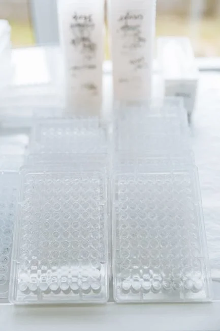
Cationic polyacrylamide (CPAM) is the standard flocculant for cement sludge because the negatively charged C-S-H particles and CaCO3 surfaces demand a positively charged polymer to bridge and neutralize. Charge density in the 50–80% range and molecular weight of 8–12 MDa give the best balance between floc strength (high MW) and charge neutralization (mid-to-high CD). The dose window is 2–6 kg/tonne dry solids — most plants start at 4 kg/t DS on first commissioning and optimize downward.
The two optimization levers every operator should run are jar testing and Capillary Suction Time (CST). A target CST under 20 seconds (down from a raw sludge baseline that often exceeds 200 seconds for cement sludge) indicates the polymer is breaking the gel structure and freeing the bound water. Cake solids above 28% with a CST under 15 seconds is the realistic 2026 target for a filter-press operation. Most first-year plants over-dose by 30–50% because the operator adds polymer until the filtrate runs clear, which is a lagging indicator — by the time the filtrate is clean, the polymer is in excess and the cake is rubbery. Run a CST curve before the next polymer drum is ordered.
For high-alkalinity streams with elevated soluble metals, dose ferric chloride at 50–200 mg/L ahead of the polymer. FeCl3 precipitates metals and reduces polymer demand by 20–40% because the metal-hydroxide flocs already provide a large, dense surface for the polymer to bridge (HydropureWater field data, 2026). The automatic chemical dosing skid on this site eliminates the operator-prep error — incomplete polymer hydration is the single most common cause of filter-cloth blinding incidents we observe in cement plant audits.
| Stream | Polymer type | Charge density | MW (MDa) | Dose (kg/t DS) | Coagulant (if used) | Target CST (s) |
|---|---|---|---|---|---|---|
| Kiln scrubber sludge | CPAM | 60–80% | 10–12 | 3–5 | FeCl3 100–200 mg/L | < 15 |
| Mill wash water sludge | CPAM | 50–70% | 8–10 | 2–4 | FeCl3 50–100 mg/L | < 20 |
| Combined plant sludge | CPAM | 60–80% | 10–12 | 3–6 | FeCl3 75–150 mg/L | < 20 |
Compliance Mapping: EPA NESHAP, EU IED BREF, and 2026 Discharge Limits
The treatment train must hit specific numeric limits to be permissible. The table below maps the major 2026 regulatory anchors to the unit operation that delivers compliance. Two points engineers consistently miss: mercury removal to the 0.011 mg/L NESHAP limit requires sulfide precipitation (NaHS or FeS at 5–20 mg/L as S) ahead of clarification, not just coagulant; and pH neutralization to 6–9 is non-negotiable before any biological polishing step because alkalinity above 9.5 will collapse nitrification and promote scaling in aeration basins. For comparison with adjacent heavy-industry trains, see the foundry wastewater sludge treatment guide and the coking wastewater sludge treatment guide.
| Regulation | Parameter | Limit | Achieving unit operation |
|---|---|---|---|
| EPA NESHAP 40 CFR 63 Subpart LLL | Hg in kiln wastewater | ≤ 0.011 mg/L | NaHS/FeS precipitation + DAF |
| EPA NESHAP 40 CFR 63 Subpart LLL | PM from kilns | ≤ 0.02 lb/ton clinker | Baghouse on kiln (pre-treatment) |
| EU IED 2010/75/EU BREF (Cement & Lime) | COD to surface water | < 50 mg/L | Biological polishing (MBR/SBR) |
| EU IED 2010/75/EU BREF (Cement & Lime) | TSS to surface water | < 30 mg/L | DAF/lamella + filtration |
| EU IED 2010/75/EU BREF (Cement & Lime) | Hg to surface water | < 0.05 mg/L | Sulfide precipitation |
| EU IED 2010/75/EU BREF (Cement & Lime) | pH | 6–9 | CO2 or H2SO4 neutralization |
| China GB 30485-2013 + GB 8978-1996 | pH, SS, COD (export plants) | Site-specific; commonly pH 6–9, SS < 70 mg/L | Neutralization + DAF/sedimentation |
Frequently Asked Questions
What pH is cement wastewater?
Cement wastewater typically sits at pH 12–13 straight out of kiln and clinker cooler dust collector scrubbers, driven by calcium hydroxide carry-over from the lime (CaO) in the raw mix. Raw and finish mill wash water runs pH 9–11, and ready-mix truck washout ranges pH 11–13. The wastewater must be neutralized to 7–9 (or 6–9 under EU IED BREF) before biological treatment, clarification, or discharge.
What cake dryness can a filter press achieve on cement sludge?
A hydraulic automatic plate-and-frame filter press with polymer conditioning typically achieves 28–35% dry solids on cement sludge, versus 22–28% for a decanter centrifuge, 18–22% for a belt press, and 18–24% for a screw press. The higher cake dryness from a filter press cuts hauling weight, lowers landfill tipping fees, and is the typical specification where kiln co-processing is the disposal route.
Which polymer works best for cement kiln dust sludge?
Cationic polyacrylamide (CPAM) with 60–80% charge density and 8–12 MDa molecular weight, dosed at 3–5 kg per tonne dry solids, is the standard. The cationic charge neutralizes the negative surface charge on calcium silicate hydrate (C-S-H) and CaCO3 particles, while the high molecular weight bridges fines into a filterable floc. Dose is optimized by Capillary Suction Time (CST) targeting under 15 seconds and cake solids above 28%.
Is cement wastewater sludge hazardous under RCRA?
Most cement wastewater sludge is not characteristically hazardous under RCRA, but it can be classified as a non-hazardous industrial waste (or, in some U.S. states, a special waste) when leachable metals exceed state thresholds. TCLP testing on the filter cake is required to confirm status, and plants in the U.S. should also check state-level limits for mercury and lead because these are tighter than the federal NESHAP effluent limits in several jurisdictions.