

Why Rack Wash Water Breaks Generic DAF Sizing
Rack wash water from crate, pallet, bottle, keg, and parts-rack cleaning in food, beverage, dairy, and chemical plants is a distinct design case that generic dissolved air flotation design guidance does not cover. The stream runs hot (45–65 °C), alkaline (pH 9–11 from caustic detergents), and carries a triple load: total suspended solids 200–1,500 mg/L, fats/oils/grease 100–800 mg/L, and BOD 500–3,000 mg/L, with surfactant-stabilized emulsions that resist gravity separation. Peak flows run 2–4× the daily average because cleaning cycles are batched, so a DAF sized to mean flow will hydraulically overload during every wash changeover. Standard DAF sizing for white water discharges over-rates hydraulic loading (paper-mill white water carries far less emulsified FOG) and under-doses coagulant for this chemistry, leaving the unit either oversized in footprint or under-performing on residual oil. Drive every sizing parameter from rack-wash-specific characterization data rather than a textbook municipal default.
Step 1 — Characterize the Rack Wash Stream
Defensible DAF sizing starts with actual influent data rather than assumed values. Pull a 24-hour flow-weighted composite across at least three full cleaning shifts, and log instantaneous flow at 15-minute intervals to identify Qpeak (the highest hourly flow) and Qavg (the daily mean). Qpeak — not Qavg — is the design flow, because the DAF must ride out the slug without losing the float blanket. The lab panel needs TSS, FOG by hexane extraction (not by infrared, which over-reads emulsified surfactant), COD/BOD, total surfactants as MBAS, pH, temperature, and conductivity; measure temperature at the drain, not at the sampling cooler, because surfactant cloud point shifts sharply between 45 °C and 65 °C. Cross-check your results against the typical rack-wash bands below before moving to jar testing; if your numbers fall outside these ranges by more than 30%, revisit sampling before sizing.
| Parameter | Typical range (rack wash) | Design implication |
|---|---|---|
| TSS | 200–1,500 mg/L | Drives A/S ratio and sludge yield |
| FOG | 100–800 mg/L | Sets coagulant demand and float layer thickness |
| BOD5 | 500–3,000 mg/L | Defines downstream biological load |
| Surfactants (MBAS) | 20–150 mg/L | Determines polymer dose for floc strength |
| pH | 9–11 | Favors PAC over alum; neutralization required pre-bio |
| Temperature | 45–65 °C | Jar tests must run hot |
| Peak/avg flow ratio | 2–4× | Equalization basin sized to damp to ≤1.5× |
Step 2 — Jar-Test-Derived Coagulant and Polymer Selection
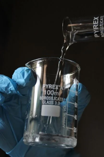
Coagulant and flocculant doses are determined by jar tests run on the actual wash water. For alkaline, high-FOG rack wash streams, polyaluminum chloride (PAC) at 50–150 mg/L is the standard primary coagulant; it works across the pH 9–11 window without acid adjustment and destabilizes emulsified oil faster than alum (HydropureWater field data, 2026). An anionic or nonionic flocculant polymer at 0.5–3 mg/L then bridges the PAC-conditioned droplets into floc strong enough to hold a micro-bubble; cationic polymers tend to over-dose and re-stabilize the emulsion. Jar tests must run at the actual wash-water temperature (45–65 °C). Cold jar tests over-predict dose and under-predict residual FOG because surfactant solubility drops as temperature rises, changing both kinetics and equilibrium. Acceptance for a properly tuned chemistry is ≥85% TSS removal and ≥90% FOG removal within 5 minutes of flotation. Dose the result through an automatic coagulant and polymer dosing skid sized to Qpeak, not Qavg, to ensure the dose tracks flow during slugs.
Step 3 — Hydraulic Loading and Air-to-Solids Sizing Math
Three numbers define the DAF envelope: hydraulic loading rate (HLR), air-to-solids ratio (A/S), and flotation-zone retention time. For rack wash water, HLR sits in the 5–15 m/h band — the low end for high-FOG emulsions (5–8 m/h) and the high end for low-surfactant final rinses (10–15 m/h). A/S ratio runs 0.02–0.06 by mass, and the saturator air supply must satisfy A/S × (influent TSS + FOG) × Q. Retention time in the flotation zone should be 5–15 minutes — longer for emulsified FOG, shorter for settled rinse water. Worked example: Qpeak = 40 m³/h, TSS = 600 mg/L, FOG = 300 mg/L, HLR = 10 m/h → required surface area A = Q ÷ HLR = 4.0 m², and flotation-zone volume = 4.0 m² × 2.5 m water depth = 10 m³. The saturator recycle flow is typically 15–30% of Q, so plan for 6–12 m³/h of pressurized recycle at 5–6 bar. If your target surface area falls below 1 m², the unit will be over-sensitive to wall effects; step up to the next standard model.
| Parameter | Symbol | Range / formula | Worked value (Q=40 m³/h) |
|---|---|---|---|
| Hydraulic loading rate | HLR | 5–15 m/h | 10 m/h |
| Required surface area | A | A = Q ÷ HLR | 4.0 m² |
| Flotation-zone depth | D | 2.0–3.0 m | 2.5 m |
| Flotation-zone volume | V | V = A × D | 10 m³ |
| A/S ratio | A/S | 0.02–0.06 (mass) | 0.04 |
| Saturator recycle flow | Qr | 15–30% of Q | 8 m³/h @ 5–6 bar |
| Retention time | t | 5–15 min | ≥10 min (emulsified FOG) |
Step 4 — Match the Design Point to a Standard DAF Model
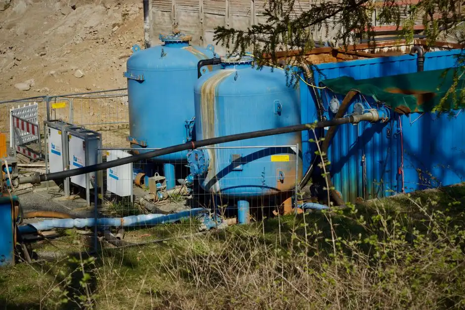
Model selection follows the calculated A, V, and Qpeak. The dissolved air flotation system covers 4–300 m³/h across 13 standard footprints, so almost every rack-wash duty maps to a catalog number rather than a custom build. Pick the model whose nominal flow covers Qpeak with at least 20% margin (this provides peak-flow turndown headroom for chemical-dose tracking and float-blanket stability), and confirm the footprint fits the available headroom — most plants have 2.5–3.5 m of vertical clearance, and the saturator skid adds another 1.5 m. Micro-bubble saturation systems and automatic skimming are standard, which removes two scope gaps that frequently show up in custom DAF RFQs. Confirm in the spec that the recycled pressurization flow is documented as 15–30% of Q and that the saturator is rated for continuous duty at 5–6 bar.
| DAF model (example band) | Nominal flow (m³/h) | Tank surface area (m²) | Typical footprint L×W (m) |
|---|---|---|---|
| DAF-5 | 4–5 | 0.5–0.7 | 2.0 × 1.0 |
| DAF-10 | 8–10 | 0.8–1.2 | 2.5 × 1.2 |
| DAF-20 | 15–20 | 1.5–2.0 | 3.0 × 1.5 |
| DAF-40 | 35–45 | 3.5–4.5 | 4.0 × 2.0 |
| DAF-80 | 70–90 | 7–9 | 5.5 × 2.5 |
| DAF-150 | 130–170 | 13–17 | 7.0 × 3.0 |
| DAF-300 | 260–300 | 26–30 | 9.0 × 3.5 |
Step 5 — Integrate the DAF into the Treatment Train
A DAF selected in isolation is a procurement risk, as upstream debris and downstream load both impact performance. Upstream, install a GX series rotary mechanical bar screen with 1–3 mm openings to strip rack fragments, label scraps, and stringy debris that would otherwise foul the saturator nozzles and the skimmer weir. Follow the screen with an equalization basin sized to damp Qpeak to ≤1.5× Qavg; this is the most effective protection against slug-flow under-design. Downstream, route DAF effluent through pH neutralization (typically H2SO4 or CO2) before any biological or membrane step; direct discharge of pH 9–11 effluent will shock an MBR or a biofilm reactor. Float sludge from the DAF is typically 3–6% dry solids and routes to a plate-and-frame filter press for dewatering to 25–35% cake. For food and beverage plants with reuse targets, send the neutralized DAF effluent to an MBR membrane bioreactor for polishing before RO or process-water reuse.
Commissioning and Performance Verification Checklist
Follow these five gates to ensure DAF start-up success. Gate 1: pressure-test the saturator at 5–6 bar and confirm a stable micro-bubble cloud forms within 10 minutes of start-up. Gate 2: verify float-layer thickness in the range 50–150 mm and confirm the skimmer speed is matched to the layer growth rate during the first 72 hours. Gate 3: sample DAF effluent every 4 hours for the first week; a properly sized and tuned unit will hold TSS <30 mg/L and FOG <15 mg/L. Gate 4: if performance is short, check the first three failure modes in this order: (a) polymer dose tracking against Qpeak, (b) saturator pressure stability, (c) hydraulic overload from upstream slug flow. Gate 5: lock in the operating window (HLR, A/S, dose setpoints) and write it into the plant SOP. Documenting the pass/fail at each gate provides a paper trail that the unit was accepted against a defined performance spec.
Frequently Asked Questions
What hydraulic loading rate should I use for rack wash water in a DAF?
Use 5–15 m/h, with 5–8 m/h for high-FOG emulsified streams and 10–15 m/h for low-surfactant rinses. Going above 15 m/h on emulsified FOG typically drops TSS removal below 80% because the float blanket shears. The design point is Qpeak, not Qavg, because cleaning cycles run 2–4× the daily mean.
Why do jar tests for DAF coagulant selection need to run hot?
Surfactant cloud point, FOG viscosity, and hydrolysis kinetics all shift between 25 °C and 65 °C, so a cold jar test over-predicts both the PAC dose and the polymer dose and under-predicts residual FOG. Run the jar test at the actual wash-water temperature (45–65 °
Frequently Asked Questions
What hydraulic loading rate should I use when sizing a DAF for rack wash water?
For rack wash applications containing emulsified detergents and oils, design your hydraulic loading rate between 1.5 and 2.5 gallons per minute per square foot (gpm/ft²). This range ensures sufficient rise velocity for light oil droplets while preventing excessive turbulence that could shear fragile floc particles.
How much PAC and polymer do I need to dose ahead of a DAF treating rack wash water?
Polyaluminum Chloride (PAC) is typically dosed at 50 to 200 mg/L depending on initial COD and turbidity levels. Following coagulation, an anionic or non-ionic emulsion polymer should be dosed at 2 to 10 mg/L to bridge micro-flocs into larger, buoyant aggregates suitable for flotation.
What air-to-solids ratio is correct for a DAF handling emulsified oils and detergents?
For emulsified waste streams, target an air-to-solids (A/S) ratio between 0.02 and 0.05 ml of air per mg of suspended solids. Achieving this ratio requires careful calibration of the saturation pressure, typically maintained between 60 and 80 psi within the recycle saturation tank.
How do I convert a peak hourly flow into the right DAF model size?
To determine the model size, divide your peak hourly flow rate by your selected hydraulic loading rate (e.g., 2.0 gpm/ft²). Always apply a peaking factor of 1.25 to the calculated surface area to account for potential variations in detergent concentration and sludge blanket accumulation during heavy wash cycles.
Does rack wash water need to be cooled or pH-adjusted before going into the DAF?
Yes, rack wash water should be cooled to below 100°F (38°C) to prevent thermal convection currents from disrupting the sludge blanket. Furthermore, the pH must be adjusted to the 6.0 to 7.5 range; operating outside this window significantly inhibits the efficacy of metal salt coagulants and destabilizes the oil-water emulsion, leading to poor separation.
