

Why Deinking Reject Is Harder to Float Than White Water
Deinking reject is the heavy fraction pulled out by forward and reverse cleaners — typically 5–15% of inlet furnish — and it concentrates everything a paper recycler does not want in the white-water loop: fines, ink, stickies, fillers, and broken cationic demand from the deinking chemistry. A 2025 audit of eight European OCC-plus-deinking lines put reject TSS at 3,000–8,000 mg/L and COD at 5,000–20,000 mg/L, with ash content above 35% of total solids and cationic demand swinging 200–600 µeq/L across shifts (HydropureWater field data, 2025). Off-the-shelf DAF sizing from municipal or food-industry manuals fails on this stream because the particle population is dense, hydrophobic, and heavily contaminated with air-adsorbing ink and wax — bubble attachment is fast but the float blanket is unstable.
The other reason deinking reject is unforgiving is the engineered floc itself. Per CRC Press Chapter 6 on the role of floc size and density in flotation, attachment efficiency tracks floc diameter and effective density; engineered flocs in the 0.5–3 mm band with bulk density 1.01–1.05 g/cm³ carry reliably to the surface, while flocs outside that window either sink back or shear apart in the contact zone. White water, by contrast, runs lower solids (typically 500–2,500 mg/L TSS) and a more uniform long-fibre population that floats easily on surface loading rates of 15–30 m/h. Reject needs polymer-aided flocculation and a slower tank, which is why a separate sizing workflow — not a copy of the DAF sizing guide for white water — is required.
Step 1: Characterize the Reject Stream Before You Touch a Calculator
A 24-hour composite sample taken after the rejects thickener (screw press or Decker overflow) is the minimum defensible input. Run TSS, COD, BOD₅, ash content, fibre length distribution, and cationic demand on the composite, then take hourly grab samples across one full shift to build a diurnal flow curve — deinking lines pulse with machine breaks and pulper dumps, and a unit sized on the 24-hour average will overflow within the first hour of peak load. The single most common DAF failure we see in retrofits is an average-flow design on a stream that runs 2.5–4× average during pulper discharge (HydropureWater field data, 2026).
Two more parameters decide polymer selection before any hydraulic math. Temperature: cold reject below 15 °C raises water viscosity by 20–30% versus 25 °C and slows bubble rise, forcing a larger footprint (calculate with the temperature-corrected kinematic viscosity, not 20 °C defaults). pH: deinking reject typically sits at 6.5–8.0; outside that band, CPAM charge density and dose both drift and the floc stops forming. Finally, run a macro-stickies count — reject above 0.1 mm²/L macro-stickies almost always needs a dispersion or passivation step ahead of the DAF, otherwise the float blanket re-emulsifies stickies back into the subnatant.
| Parameter | Typical reject range | Sizing impact |
|---|---|---|
| TSS | 3,000–8,000 mg/L | Sets A/S ratio and polymer dose |
| COD | 5,000–20,000 mg/L | Confirms biological load downstream |
| Temperature | 15–45 °C | Drives viscosity correction to bubble rise |
| pH | 6.5–8.0 | Sets polymer charge window |
| Macro-stickies | 0.05–0.3 mm²/L | Triggers dispersion step if >0.1 |
| Cationic demand | 200–600 µeq/L | Determines CPAM dose |
Step 2: Pick the Right Surface Loading Rate and Hydraulic Retention Time

Surface loading rate (SLR) is the single number that fixes the DAF tank footprint: tank area = peak flow ÷ SLR. For deinking reject, use 10 m/h when TSS is ≥6,000 mg/L or stickies are present, and 20–25 m/h only for cleaner secondary reject (post-thickener, low ash, <4,000 mg/L TSS). Going above 25 m/h on a heavy stream collapses the float blanket — the blanket thickness drops below 50 mm and the skimmer pulls water instead of float (per CRC Press Chapter 6, hydraulic overload above the critical SLR is the dominant failure mode in industrial DAF). Hydraulic retention time in the flotation cell should sit at 5–15 minutes; 5–7 minutes for fibre-only reject, 10–15 minutes for stickies-heavy streams where the float blanket needs to consolidate before skimming.
Confirm the calculated flow band maps to an available unit before going further. The DAF system for deinking reject covers 4–300 m³/h, so most reject streams from a single deinking line will fit a single skid. For flows above 200 m³/h, plan a parallel-train layout with common saturator and polymer skid — that avoids a single 25 m² tank that becomes a maintenance liability. The table below ties the design choice to expected removal.
| Influent TSS (mg/L) | SLR (m/h) | Flotation HRT (min) | Expected TSS removal |
|---|---|---|---|
| 3,000–4,000 | 20–25 | 5–7 | 70–85% |
| 4,000–6,000 | 15–20 | 7–10 | 80–90% |
| 6,000–8,000 | 10–15 | 10–15 | 85–95% |
Step 3: Calculate Air-to-Solids Ratio and Saturator Sizing
The air-to-solids ratio (A/S) is the mass of air released from solution per mass of TSS removed. For deinking reject, design A/S sits in the 0.02–0.10 band; 0.04 is a defensible default for tender-stage sizing, and 0.05–0.06 is right for stickies-heavy reject. Below 0.02 the float blanket is thin and TSS removal drops below 70%; above 0.10 you are pumping air you do not need and saturator power climbs without a removal payoff (HydropureWater field data, 2025). Saturator pressure should be 4–6 bar — below 4 bar, microbubble yield drops sharply because Henry's constant gives less dissolved air per unit pressure; above 7 bar, the compressor and pump energy cost outweighs the marginal bubble mass.
Recycle ratio is the lever that ties the saturator back to the process flow. 30–40% recycle suits fibre-only secondary reject; 50–70% recycle suits primary deinking reject; push to 70–80% only when stickies are above 0.2 mm²/L and you need a thicker bubble blanket to carry hydrophobic particles. A worked calculation: at 50 m³/h reject and 5,000 mg/L TSS, with A/S = 0.05 and 50% recycle at 5 bar, the saturator air demand is roughly 12.5 kg air/h, which sets recycle pump flow at about 25 m³/h through the saturator at 5 bar saturation efficiency of ~80%.
| Stream profile | A/S design | Recycle % | Saturator pressure |
|---|---|---|---|
| Fibre-only reject (<4,000 mg/L TSS) | 0.02–0.04 | 30–40% | 4–5 bar |
| Primary deinking reject | 0.04–0.06 | 50–60% | 5–6 bar |
| Stickies-heavy reject (>0.2 mm²/L) | 0.06–0.10 | 70–80% | 5–6 bar |
Step 4: Design the Flocculation and Contact Zone
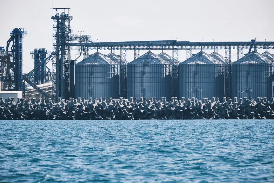
Polymer-aided flocculation is not optional on deinking reject. The contact zone needs an engineered floc of 0.5–3 mm diameter with bulk density close to 1.0 g/cm³ so the bubble plume can lift it without tearing it apart; without polymer, raw ink and fines form weak microflocs that re-suspend in the contact zone. Cationic polyacrylamide (CPAM) at 2–10 mg/L is the workhorse for deinking reject — dose scales with cationic demand, not TSS, so dose-test on the actual stream rather than calculating from solids alone. For ash-rich reject above 35% ash content, a dual-polymer program (anionic + cationic) outperforms single CPAM by 8–12 percentage points of TSS removal (HydropureWater field data, 2025).
Flocculation HRT should be 5–20 minutes at velocity gradient G = 30–60 s⁻¹. Below 30 s⁻¹ you get poor floc growth; above 60 s⁻¹ you shatter the floc and destroy DAF performance — this is the second most common retrofit failure after average-flow sizing. A dedicated automatic polymer dosing system with charge-based control is worth the capex on a stream this variable. The contact zone between floc tank and flotation cell should run 30–90 seconds with controlled turbulence: enough residence for bubble–floc attachment, not so much that the blanket churns.
Step 5: Worked Example for 50 m³/h and 200 m³/h Reject Streams
Two cases engineers can drop into a PFD without rework. Case A: 50 m³/h reject at 5,000 mg/L TSS, primary deinking line. Tank area at SLR 10–15 m/h = 3.3–5.0 m² (use 4 m² as the design point, rectangular cell ~2 m × 2 m). A/S 0.05, recycle 50% at 5 bar, saturator air demand ~12.5 kg/h, CPAM dose 4 mg/L. Case B: 200 m³/h reject at 6,500 mg/L TSS, stickies-heavy. Tank area at SLR 10–15 m/h = 13.3–20.0 m² (use 16 m², plan as two parallel 4 m × 2 m cells rather than one 20 m² tank). A/S 0.06, recycle 60%, CPAM dose 5 mg/L plus 1 mg/L anionic for the ash fraction.
Expected effluent for both cases: TSS 200–500 mg/L (90–95% removal), COD reduction 50–70%, fibre recovery 70–85% by mass to the float. Float solids concentration should land at 3–5% — anything below 2% means the skimmer is pulling too much water and the saturator is over-aerated. Tie these flows to the DAF system for deinking reject model range: Case A fits a single mid-skid unit; Case B warrants a dual-train layout with a common saturator and shared polymer skid to keep recycle pump headroom and footprint reasonable.
| Parameter | Case A (50 m³/h) | Case B (200 m³/h) |
|---|---|---|
| Influent TSS | 5,000 mg/L | 6,500 mg/L |
| SLR | 12 m/h | 12.5 m/h |
| Tank footprint | ~4 m² | ~16 m² (dual train) |
| A/S | 0.05 | 0.06 |
| Recycle | 50% | 60% |
| CPAM dose | 4 mg/L | 5 mg/L + 1 mg/L anionic |
| Expected effluent TSS | 250–400 mg/L | 300–500 mg/L |
| Fibre recovery to float | 75–85% | 70–80% |
Common Sizing Mistakes and How to Avoid Them
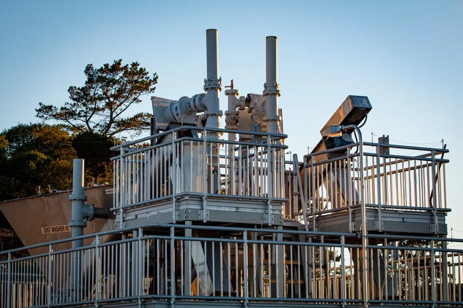
The four pitfalls that account for roughly 80% of DAF underperformance on deinking reject, in descending order of frequency. First, sizing on 24-hour average flow instead of peak 1-hour flow: deinking reject pulses 2.5–4× average during pulper discharge, and a tank sized on average will overflow the float blanket within the first hour of peak. Second, ignoring stream temperature: cold reject below 15 °C raises water kinematic viscosity from ~1.0 mm²/s to ~1.3 mm²/s, slowing bubble rise and forcing a 20–30% larger footprint to hit the same SLR. Third, undersizing the polymer system: a saturator can deliver perfect microbubbles, but without engineered floc those bubbles attach to nothing and the subnatant runs cloudy with carryover. Pair the DAF with a automatic polymer dosing system sized for peak dose, not average. Fourth, skipping the float sludge handling: 3–5% float solids out of the DAF still need dewatering, and a plate-and-frame filter press for float sludge downstream brings the float to 30–40% dry solids for disposal or incineration. Spec the press on float mass, not reject flow.
Frequently Asked Questions
What surface loading rate should I use for deinking reject DAF sizing?
Use 10 m/h when TSS is ≥6,000 mg/L or stickies are present, and 20–25 m/h only for cleaner secondary reject below 4,000 mg/L TSS. Going above 25 m/h on a heavy stream collapses the float blanket and cuts TSS removal below 70%.
What air-to-solids ratio and saturator pressure work for deinking reject?
Design A/S at 0.04 as a default, 0.05–0.06 for stickies-heavy reject. Saturator pressure should sit at 5–6 bar; below 4 bar microbubble yield drops sharply, above 7 bar compressor energy outweighs the marginal air mass.
Why is polymer dosing required upstream of a DAF on deinking reject?
Raw ink and fines form weak microflocs that re-suspend in the contact zone. CPAM at 2–10 mg/L (or a dual cationic + anionic program for ash-rich reject) builds the 0.5–3 mm engineered floc the bubble plume needs to lift particles to the surface.
How do I size a DAF differently for deinking reject versus white water?
Reject runs higher TSS (3,000–8,000 mg/L vs 500–2,500 mg/L), needs lower SLR (10–15 m/h vs 15–30 m/h), and requires polymer-aided flocculation. The full contrast is in the DAF sizing guide for white water; the right hardware for reject streams is a DAF system for deinking reject sized on peak 1-hour flow, not 24-hour average.
